What Is Line and Load in Electrical Wiring?
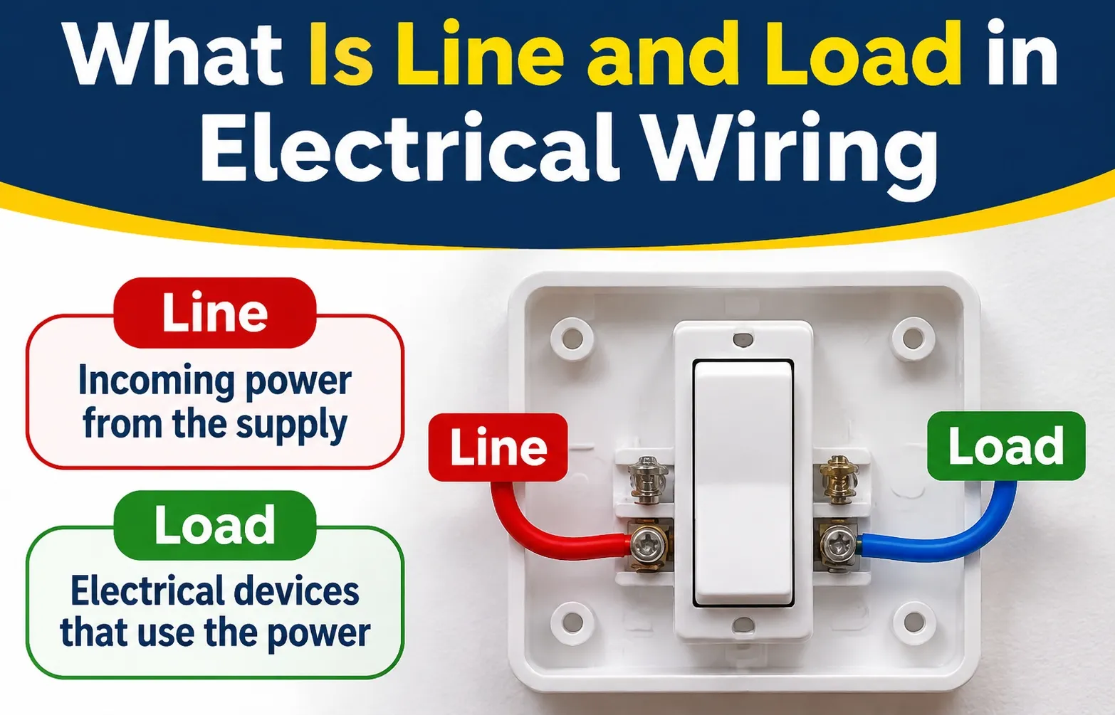 In electrical wiring, line refers to the incoming wires that bring live electrical power from the main service panel or circuit breaker into a device, while load refers to the outgoing wires that carry that power from the device to downstream outlets, lights, or appliances. Understanding this directional flow prevents tripped breakers, damaged smart switches, and Ground Fault Circuit Interrupter (GFCI) failures.
Line vs. Load Core Definitions
Every electrical box acts as a junction point along a branch circuit where electricity enters from a source and exits toward a destination. Distinguishing between the two sides comes down to where the current originates and where it travels next:
- Line (Incoming / Upstream Power): The supply side of the circuit delivering live voltage directly from the breaker panel to the first switch or receptacle.
- Load (Outgoing / Downstream Power): The distribution side of the circuit routing electricity out of the device to feed other fixtures further down the line.
What Is a Line Wire? (Incoming Upstream Power)
A line wire is the upstream conductor that supplies continuous 120-volt or 240-volt alternating current (AC) from your home’s main service panel into an electrical box. Think of the line wire like the main water supply pipe entering your house before it branches off to individual faucets.
Because the line wire connects directly back to the circuit breaker, it behaves predictably inside any electrical box:
- Always Energized: As long as the corresponding circuit breaker is switched ON, the hot line wire carries live voltage—even if the wall switch or outlet it feeds is turned off.
- Primary Power Source: Every branch circuit begins with a line connection at the breaker box and terminates at the first switch, GFCI receptacle, or junction box along the run.
- Critical Terminal Placement: Smart switches, dimmers, and GFCI outlets require incoming power on their dedicated
LINEterminals to power their internal electronics and protective sensors.
What Is a Load Wire? (Outgoing Downstream Power)
A load wire is the downstream conductor that carries electrical current away from a switch, outlet, or control device to power another fixture along the same circuit. Continuing the plumbing analogy, load wires act like the pipes running from a shutoff valve to a specific sink or showerhead.
Unlike the incoming supply side, a load wire depends entirely on the upstream device to receive electricity:
- Conditionally Energized: A load wire remains completely dead (0 volts) until the upstream switch is flipped ON or the upstream GFCI outlet is reset and closed.
- Downstream Protection: When you connect downstream standard outlets to the
LOADterminals of a GFCI receptacle, that single GFCI monitors and protects every outlet connected after it. - End-of-Run Absence: If an electrical box sits at the very end of a circuit run and does not feed any additional outlets or lights, it will contain incoming line wires but no load wires.
Essential Electrical Safety Precautions Before Working
Working inside an open electrical box exposes you to live 120V or 240V conductors capable of causing severe electrical shock, arc flashes, or electrical fires. Always follow strict safety protocols before disconnecting or testing any wires:
- Shut Off Power at the Breaker Panel: Flip the specific circuit breaker to the OFF position—never rely solely on turning off a wall switch, as the line wire inside the box remains live.
- Verify Zero Voltage: Test every conductor inside the electrical box with a reliable non-contact voltage tester or digital multimeter before touching bare copper or brass screw terminals.
- Use Insulated Tools and Gear: Wear rubber-soled shoes, work on dry surfaces, and handle conductors using tools with intact VDE-rated insulated grips.
- Consult a Licensed Electrician: If you encounter damaged insulation, aluminum branch wiring, or unfamiliar multi-wire configurations, stop immediately and hire a certified electrician.
Line vs. Load Comparison Table
Comparing line and load side by side makes it easy to identify how electricity enters and exits any electrical box. While both sides use identical copper conductors inside standard Romex cable, their electrical behavior, voltage potential, and terminal screw connections operate in opposite directions along a branch circuit.
Line vs. Load at a Glance
The reference matrix below outlines the exact functional differences between the upstream supply side and the downstream distribution side of a standard residential circuit:
Can a Load Wire Also Act as a Line Wire?
Yes—a single physical cable routinely serves as both a load wire and a line wire depending on which electrical box you are standing in. In residential daisy-chain wiring, electricians run one continuous section of Romex cable from the load terminal screws of the first receptacle directly into the incoming side of the next receptacle down the wall.
Understanding this relative perspective eliminates confusion when troubleshooting multi-outlet circuits:
- Perspective at Outlet A (Upstream Device): The Romex cable exiting the box to feed the next room is the load because it carries outgoing current away from Outlet A.
- Perspective at Outlet B (Downstream Device): That exact same Romex cable becomes the line the moment it enters Outlet B’s electrical box, because it serves as Outlet B’s incoming power source.
- Circuit Continuity Rule: Every intermediate device along a branch circuit receives power on its line side and passes that same voltage potential forward through its load side until the circuit terminates at the final fixture.
Line vs. Load Wire Colors & Wiring Diagrams Explained
A dangerous misconception among do-it-yourselfers is that specific wire colors reveal whether a conductor carries incoming line power or outgoing load current. According to the NFPA Electrical Safety Guidelines, both incoming and outgoing cables utilize identical color-coding, making physical labeling and terminal inspection mandatory for safe residential wiring.
Why Wire Color Alone Does Not Tell You Line vs. Load
Standard residential wiring uses uniform color codes mandated by the National Electrical Code (NEC) to identify the function of individual conductors. However, wire color provides zero indication of whether a specific cable is feeding power into a device or carrying it away:
- Identical Conductor Colors: Both an incoming Line cable and an outgoing Load cable inside standard Romex bundles contain the exact same black (hot), white (neutral), and bare copper (ground) wires.
- The Color Myth: Assuming a black wire is automatically a “line” wire will lead to dangerous miswiring, because outgoing load wires are also black when energized.
- Physical Testing Required: Because colors match across cables, you must rely on circuit tracing, multimeter voltage tests, or factory device markings to distinguish line from load.
How to Read a Line and Load Wiring Diagram
A standard electrical wiring diagram illustrates how electrical current flows sequentially through a branch circuit from the main electrical panel to individual endpoints. Tracing a daisy-chain circuit layout clarifies the exact path power takes:
- Circuit Origin: The diagram starts at the circuit breaker panel, where live conductors supply voltage to the branch circuit.
- First Protection Point: The hot and neutral wires enter the first GFCI receptacle strictly at its designated
LINEscrew terminals. - Downstream Distribution: Outgoing power leaves the GFCI through its
LOADterminals, continuing onward to feed a second standard downstream outlet or light fixture.
Physical Clues Inside the Box & on Devices
Manufacturers stamp explicit guides directly onto modern safety devices to help electricians and homeowners avoid wiring mistakes. Examining the physical hardware reveals several reliable indicators:
- Stamped Terminal Labels: GFCI and AFCI receptacles feature permanent embossed text reading
LINEandLOADdirectly adjacent to their respective terminal screws. - Screw Color Conventions: Brass screw terminals handle hot conductors (split between line and load), while silver screw terminals handle neutral conductors.
- Factory Yellow Warning Tape: Brand-new GFCI outlets ship with bright yellow warning tape physically blocking access to the
LOADterminals to ensure installers connect incoming power to the line side first.
How to Determine Line and Load Wires Safely with a Multimeter or Tester
When opening an electrical box with multiple cables, figuring out which wire brings incoming power and which carries outgoing current requires systematic testing. Using a digital multimeter or non-contact voltage tester ensures you correctly identify both conductors while preventing accidental short circuits.
Tools You Need Before Starting
Gather the proper diagnostic equipment and safety gear before touching any electrical components inside the box:
- Digital Multimeter: Essential for measuring exact 120 volts AC potentials and performing continuity testing to verify circuit paths.
- Non-Contact Voltage Tester (NCVT): A fast, handheld phase tester that detects live electrical fields without requiring direct metal contact.
- Insulated Needle-Nose Pliers: For safely bending, separating, and positioning conductors inside cramped junction boxes.
- Wire Nuts: Critical for capping individual exposed hot wires to maintain short circuit prevention during live testing.
- Red and Black Electrical Tape: Used to clearly label and distinguish your line and load cables once identified.
Step-by-Step Live Testing Procedure (5-Step Safety Protocol)
Testing live wires requires strict adherence to safety protocols to prevent arc flashes, shock hazards, or unwanted voltage drop across your testing equipment. Follow this standardized procedure:
- Shut Off the Circuit Breaker: Flip the designated circuit breaker to the OFF position at your main service panel and confirm zero power at the device using your voltage tester.
- Disconnect and Cap All Wires: Separate all conductors and cap every exposed black hot conductor individually with wire nuts. This critical short circuit prevention step ensures bare copper cannot touch the metal box or ground wire when power is restored.
- Temporarily Restore Power: Turn the circuit breaker back on at the main panel. Keep your hands, body, and tools completely clear of the interior of the electrical box while power is active.
- Test Each Conductor: Test each capped black wire against the white neutral or bare ground using your digital multimeter set to 120 volts AC (or probe near the cap with an NCVT phase tester). The cable reading full live voltage is your incoming Line wire, while the dead cable reading zero volts is your outgoing Load wire.
- Label and Turn Off Again: Shut the circuit breaker back off at the main panel. Wrap a piece of colored electrical tape around your verified Line wire so you can easily match it to the device’s designated terminals during final assembly.
Advanced Troubleshooting: Identifying Line and Load in Multi-Wire Boxes (3+ Cables)
Opening an electrical box to find three or four separate Romex cables bundled together—often called box spaghetti—can quickly overwhelm DIYers who only expect a simple one-in, one-out wiring layout. Properly mapping these multi-cable junction boxes requires systematic isolation and a clear understanding of parallel branch circuits.
Why Some Electrical Boxes Have 3 or More Cables
Residential wiring rarely follows a single straight line from the breaker panel to every individual outlet. Instead, electricians utilize parallel branch circuits and multi-cable junction boxes to distribute power efficiently across multiple rooms and fixtures.
- Multiple Outgoing Feeds: A single incoming line cable from the breaker panel frequently feeds two or more separate outgoing load branches, sending power to adjacent rooms or downstream wall switches.
- Junction Box Splitting: The box may act as a passive distribution hub where power splits in multiple directions without a device being wired into the middle of the run.
- Switched Receptacle Legs: Additional cables inside the box often connect wall switches, half-hot outlets, or multi-location lighting configurations that require dedicated traveler or switch-leg conductors.
How to Isolate and Pigtail Multi-Wire Boxes
When working with a multi-cable junction box, attempting to cram multiple wires directly under a single screw terminal will violate junction box fill capacity rules, cause loose connections, and create severe fire hazards. Proper pigtail wiring safely bundles outgoing loads together while feeding the device from a single reliable source.
- Shut Off Power and Unbundle All Conductors: Turn off the circuit breaker, verify zero voltage with a multimeter, and remove all wire nuts so every black hot wire stands completely isolated from the others.
- Identify the True Line Cable: Turn the circuit breaker back on temporarily, test each isolated black wire with your non-contact voltage tester or multimeter against neutral, and mark the single cable reading 120V as your main Line.
- Shut Power Off and Construct a Pigtail: Turn the breaker back off. Gather all outgoing load cables together, insert them into a certified wire connector alongside a short 6-inch jumper wire (the pigtail), and twist tightly.
- Connect the Pigtail to the Device: Connect the free end of your pigtail jumper directly to the device’s
LINEterminal, and connect your verified incoming Line wire to the remaining line slot or device feed. - Verify Terminal Security: Ensure no copper strands are exposed outside the wire connectors or screw terminals.
Verification: Tug firmly on each wire inside the connector; no conductor should slip or pull loose.
Common Trap: Switched Hot Wires Mistaken for Load Wires
A frequent error during multi-cable troubleshooting is misidentifying a switched hot wire or a 3-way switch traveler as a standard downstream load cable. These conductors change their voltage state dynamically when wall switches are flipped, creating false readings during testing.
- Half-Hot Outlet Legs: Outlets where the top half is controlled by a wall switch contain a dedicated switch leg that carries voltage only when the wall toggle is flipped ON.
- Traveler Wires in 3-Way Circuits: Multi-switch hallways or stairwells feature traveler conductors that alternate voltage states between switches, easily confusing standard multimeters.
- The Toggle Test Verification: Before finalizing your wiring, test all suspected load cables while toggling every wall switch in the room or adjacent hallway on and off.
Verification: If a wire’s voltage status changes solely based on a wall switch rather than the main breaker, treat it as a switch leg or traveler rather than a standard downstream branch load.
What Happens If You Reverse Line and Load Wires?
Reversing line and load connections produces vastly different results depending on the specific electrical device installed in your wall box. While basic mechanical receptacles continue working normally when swapped, advanced safety devices and smart switches will either malfunction, fail to power up, or silently compromise your home’s electrical protection.
1. GFCI & AFCI Outlets (Critical Safety Failure)
Reversing line and load wires on a Ground Fault Circuit Interrupter (GFCI) or Arc Fault Circuit Interrupter (AFCI) creates immediate operational and safety failures. Because these devices rely on precise directional current monitoring, miswiring disrupts their internal circuitry.
- Refusal to Reset: Pressing the reset button on a miswired GFCI will often fail to latch, causing the button to immediately pop back out or stay dead.
- Constant Nuisance Tripping: The unit may trip repeatedly or fail its internal self-test routine, cutting power unpredictably.
- Silent Loss of Downstream Protection: The most dangerous failure mode occurs when the face of the GFCI appears to work and power devices plugged directly into it, but downstream outlets connected to the load terminals are left completely unprotected against ground faults.
2. Smart Switches & Dimmer Switches (No Power / Won’t Boot)
Smart switches and electronic dimmers require a continuous, uninterrupted supply of incoming power directly to their designated line terminals to operate their internal microcontrollers, radios, and relays.
- Complete Power Failure: If line and load are reversed, the smart dimmer switch will remain completely dark and unresponsive, refusing to connect to Wi-Fi or control connected lights.
- Broken Circuit Continuity: Electronic switches need stable line voltage before closing the internal circuit; wiring them backward cuts off the energy required to boot their internal operating software.
3. Standard Single-Pole Switches & Basic Duplex Outlets
Basic mechanical devices operate on simple open-and-close circuit principles that are unaffected by directional current flow.
- Normal Electrical Function: A standard single-pole switch or basic duplex outlet will function normally even if incoming and outgoing wires are reversed on their brass terminal screws.
- Split-Circuit Exceptions: If the outlet’s connecting break-off brass tab has been removed to create a split-wired outlet (where one half is switched and the other is always hot), reversing line and load will misroute switched power and disrupt intended circuit control.
Frequently Asked Questions About Line and Load Wiring
Clear answers to common questions regarding line and load connections help ensure residential electrical projects comply with safety standards and function correctly on the first attempt.
Does line or load go to the breaker?
The line wire connects directly back to the circuit breaker in your main electrical service panel. Because the breaker serves as the origin point of electrical current for that branch circuit, incoming power is always designated as the line side, never the load side.
Do I put incoming power wires on line or load?
Incoming power wires from the main panel must always connect to the designated line terminals of a device. Outgoing conductors that distribute electricity further down the branch circuit to subsequent outlets or lights connect to the load terminals.
What is load in an electrical switch?
On a wall switch, the load terminal connects to the switched hot wire running up to the ceiling fixture or appliance. This terminal carries electricity away from the switch to power the light only when the toggle switch is flipped to the ON position.
Can you put two wires on one line or load terminal?
Standard screw terminal connections accept only one wire per screw unless the device features certified dual back-wire clamp plates designed for multiple conductors. If you need to connect multiple branch cables to a single terminal, you must use a wire connector to build a pigtail.
How many outlets can you put on one electrical line (circuit)?
National Electrical Code guidelines recommend limiting a standard 15-amp breaker circuit to a maximum of 8 to 10 outlets, while a 20-amp breaker circuit safely supports 10 to 12 outlets, depending on total circuit load capacity and connected appliance wattage.

Oscar Vance | Master Plumber & Drainage Expert
Meet Oscar Vance, a licensed master plumber sharing practical solutions on residential repairs, preventive maintenance, and thoughtful home upkeep.