Direct Benchmark & Ideal HVAC Static Pressure Range
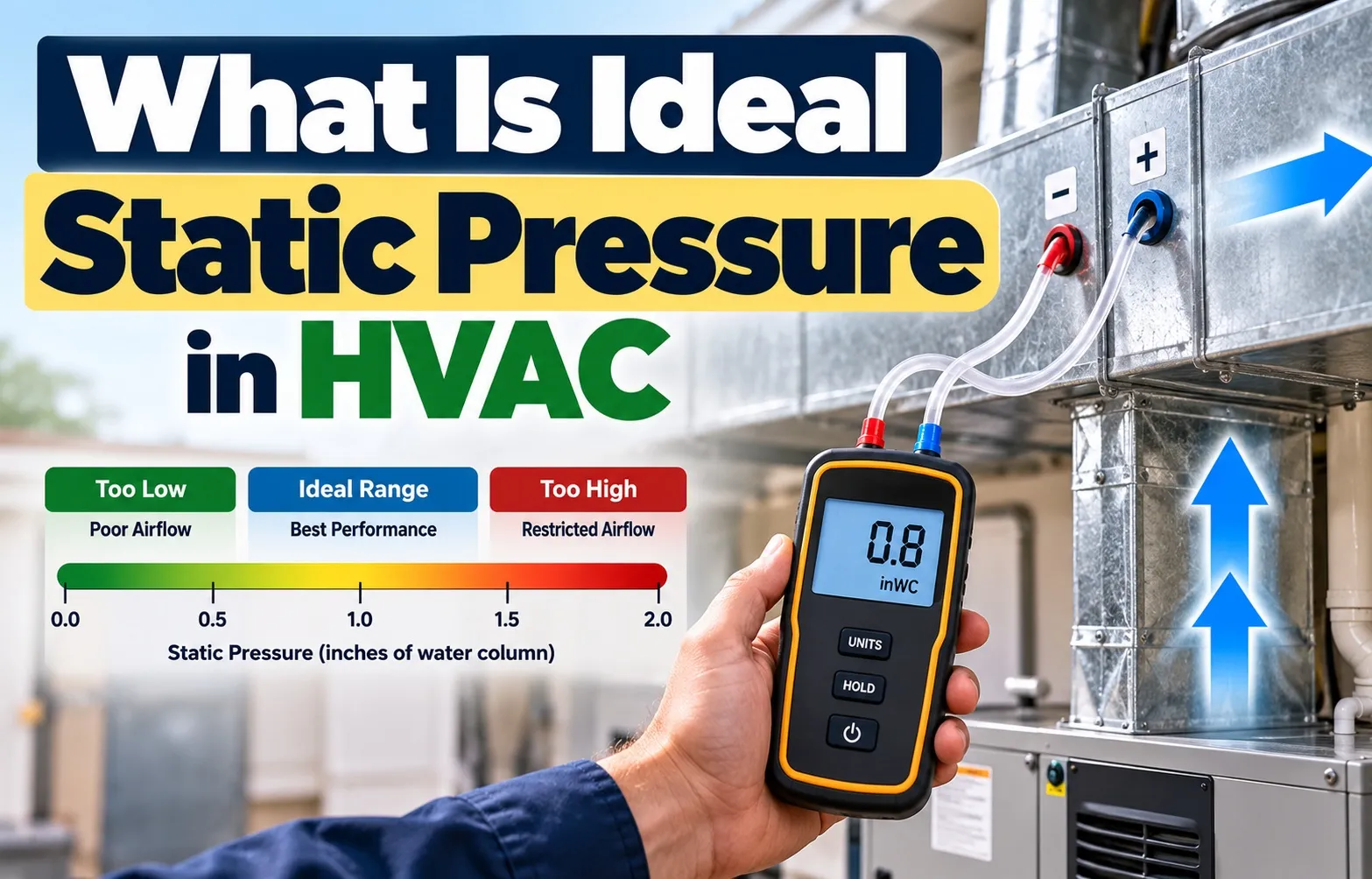 The ideal Total External Static Pressure (TESP) for a standard residential HVAC system is 0.3 to 0.5 inches of water column (in. WC), with 0.5 in. WC serving as the industry-standard maximum rating for most conventional equipment.
Maintaining total external static pressure within this target baseline ensures designed airflow delivery (measured in cubic feet per minute or CFM), prevents premature component fatigue, and maintains optimal heat transfer efficiency across indoor heating and cooling coils.
What is the Ideal Total External Static Pressure (TESP)?
Total External Static Pressure represents the total resistance to airflow created by all components attached to the air handler or furnace. This includes the supply ductwork, return ductwork, air filter, evaporator coil, and registers.
- Target Baseline: 0.3 to 0.5 in. WC provides optimal balance between airflow volume, noise levels, and equipment energy consumption.
- Absolute Operational Ceiling: 0.8 in. WC represents the typical critical upper boundary where airflow degrades rapidly, increasing risks of frozen evaporator coils or tripped limit switches.
- Diagnostic Rule: Total static pressure equals the absolute sum of supply-side static pressure and return-side static pressure: TESP = Supply Static Pressure + |Return Static Pressure|.
Field technicians must evaluate static pressure against manufacturer design parameters. Always cross-reference the unit’s data plate or technical specifications sheet attached to the air handler cabinet before making ductwork or fan speed adjustments.
Static Pressure Threshold Reference Table (0.1 to 1.0+ in. WC)
Operational static pressure measurements directly dictate system performance, energy efficiency, and equipment longevity. The following reference matrix outlines operational status across static pressure ranges:
Standard PSC Blower vs. Modern ECM Variable-Speed Motor Benchmarks
The type of blower motor installed inside the air handler changes how an HVAC system responds to high static pressure resistance.
- Permanent Split Capacitor (PSC) Motors:
- Operate at a fixed speed and direct drive output.
- When static pressure rises above 0.5 in. WC, airflow (CFM) drops sharply.
- Leads to comfort complaints, uneven cooling, and eventual coil freezing due to inadequate air volume across the coil face.
- Electronically Commutated Motors (ECM / Variable-Speed):
- Programmed to maintain constant airflow (CFM) despite resistance.
- When static pressure rises, the ECM automatically increases RPM and power output to push air through duct restrictions.
- Sustained high static pressure causes high electricity usage, loud air noise at registers, and premature control module failure.
Critical Disambiguation: Air Static Pressure vs. R-410A Refrigerant Pressure
Airflow static pressure and R-410A refrigerant pressure are two completely distinct mechanical measurements within an HVAC system, despite both utilizing the term pressure.
Homeowners and entry-level technicians frequently confuse duct airflow resistance with closed-loop refrigerant pressure. Understanding this separation prevents costly diagnostic errors, as correcting ductwork issues will not fix a chemical refrigerant imbalance, and adjusting refrigerant levels will not resolve airflow restrictions.
Understanding the Difference: Airflow Resistance vs. Refrigerant Pressure
Airflow static pressure measures the physical resistance that air encounters as it moves through ductwork, filters, and coils. It measures air volume dynamics and blower workload outside the sealed refrigeration circuit.
- Measurement Instrument: Air static pressure is measured using a specialized digital manometer equipped with static pressure probes inserted into duct plenums.
- Measurement Unit: Expressed in inches of water column (in. WC), representing small increments of pneumatic resistance.
- Refrigerant Circuit Pressure: R-410A pressure measures the internal chemical force of the refrigerant fluid as it transitions between liquid and vapor states inside sealed copper lines.
- Refrigerant Testing Tools: Tested via digital or analog manifold gauges attached directly to brass service valves on the outdoor condensing unit.
- Measurement Unit for Refrigerant: Expressed in pounds per square inch (PSI or PSIG).
While low airflow caused by high duct static pressure can secondarily lower suction line pressure by causing an evaporator coil to freeze, the two systems serve completely different operational functions.
Static Air Pressure (Ducts) vs. Line Pressures (R-410A / R-22)
Distinguishing between duct pressure dynamics and refrigeration circuit conditions requires evaluating specific measurement parameters, tools, and operational benchmarks.
How to Calculate Total External Static Pressure
Calculating Total External Static Pressure (TESP) requires measuring the pressure resistance on both the supply and return sides of the HVAC air handler. Accurate calculation enables technicians to verify whether system airflow matches the manufacturer’s specified airflow requirements.
Using a professional digital manometer and static pressure test probes ensures precise diagnostic data, identifying hidden restrictions caused by dirty coils, restrictive filters, or undersized ductwork.
The Core TESP Calculation Formula
Total External Static Pressure is calculated by summing the absolute values of the supply static pressure and the return static pressure. Because return static pressure reads as a negative value inside the return plenum, its absolute value is added to the positive supply static pressure.
- The Formula: TESP = Supply Static Pressure + |Return Static Pressure|
- Supply Static Pressure: Positive pressure measured in the supply plenum downstream of the indoor heat exchanger or evaporator coil.
- Return Static Pressure: Negative suction pressure measured in the return plenum upstream of the air filter and blower assembly.
For example, if your supply static pressure measures +0.28 in. WC and your return static pressure measures -0.22 in. WC, your total TESP equals 0.28 + 0.22 = 0.50 in. WC.
Supply Static Pressure vs. Return Static Pressure Split Rules
Understanding how static pressure budget is split between the supply and return sides helps pinpoint exactly where airflow restrictions are occurring in residential duct systems.
- Standard Split Guideline: Industry best practices recommend splitting the total static pressure budget roughly 50/50 between supply and return sides (e.g., maximum 0.2 to 0.25 in. WC per side for a 0.5 in. WC total limit).
- Return-Side Bottlenecks: In many residential systems, return static pressure accounts for over 60% of total resistance due to undersized return grilles or restrictive 1-inch media filters.
- Supply-Side Resistance: High supply resistance usually stems from sharp 90-degree flex duct bends, crushed runs, or undersized supply trunks.
Analyzing individual component drops—such as checking pressure drop across the air filter and indoor evaporator coil—isolates specific restriction points before making duct modifications.
Measurement Guide Using a Digital Dual-Port Manometer
Measuring TESP requires methodical test port placement and proper instrumentation to ensure readings reflect true system performance under operating conditions.
- Turn on Equipment: Set the thermostat to call for fan or cooling to engage the blower motor at its normal operating speed.
- Drill Test Ports: Drill 3/8-inch test holes in the ductwork. Place the return port between the air filter and the blower inlet, and place the supply port in the main supply plenum downstream of the indoor coil.
- Insert Static Pressure Probes: Insert static pressure tips into the holes, ensuring the angled tip points directly into the moving airflow stream to capture velocity pressure compensation.
- Connect Dual-Port Manometer: Connect tubing from the positive and negative ports of a digital dual-port manometer to the respective supply and return probes.
- Record and Calculate: Read the differential pressure values, combine supply and return values using the TESP formula, and compare against equipment specifications.
High vs. Low Static Pressure: Causes, Symptoms, and System Impact
High or low static pressure creates severe operational imbalances in residential HVAC systems, directly leading to comfort complaints, surging energy bills, and expensive equipment breakdowns. Recognizing these pressure anomalies early helps protect vital heating and cooling components from premature failure.
What Causes High Static Pressure? (Above 0.5 in. WC)
High static pressure occurs when airflow restrictions choke the system, forcing the blower motor to work significantly harder against excessive pneumatic resistance. This imbalance chokes air volume delivery throughout the home.
- High MERV Rating Air Filters: Installing overly dense or restrictive filters (such as MERV 13 or higher in shallow filter slots) severely chokes return air before it reaches the air handler.
- Undersized Return Grilles: Inadequate return surface area or blocked grilles starve the system of necessary intake air volume.
- Crushed or Kinked Flex Duct: Sharp 90-degree bends, pinched flex runs, or sagging duct sections obstruct smooth airflow pathways.
- Dirty Evaporator Coils: Accumulated dust, pet dander, and debris buildup on coil fins block air movement, frequently causing a frozen evaporator coil and system shutdown.
What Causes Low Static Pressure? (Below 0.3 in. WC)
Low static pressure happens when duct resistance drops below optimal parameters, often resulting from duct leakage or poor design configurations that compromise air delivery velocity.
- Leaking Supply Plenums & Disconnected Ducts: Air escaping directly into unconditioned attics or crawlspaces drops internal static resistance drastically.
- Oversized Ductwork: Duct systems that are excessively large for the blower capacity fail to build the pressure required to properly force air to distant supply registers.
- Missing Air Filters: Operating a system without an air filter removes the baseline resistance needed to regulate airflow velocity across the indoor coil.
Impact on Blower Motors: Legacy PSC Motors vs. Smart ECM Motors
Static pressure directly determines blower motor lifespan and electrical efficiency, though legacy and modern motors react to high resistance in completely opposite ways.
- Legacy PSC (Permanent Split Capacitor) Motors:
When high static pressure restricts airflow, fixed-speed PSC motors suffer a sharp reduction in cubic feet per minute (CFM). Because less air passes over the motor housing, the unit cannot dissipate heat properly, resulting in overheated PSC motor windings and frequent thermal overload trips. - Smart ECM (Electronically Commutated) Motors:
Variable-speed ECM motors are programmed to maintain constant airflow regardless of duct resistance. As static pressure climbs, the over-speeding ECM module automatically increases RPM and power output to force air through restrictions. This constant over-exertion spikes household electricity bills, generates loud whistling noises at supply registers, and frequently triggers premature electronic module burnout.
Actionable Fixes & Design Guidelines to Normalize Static Pressure
Resolving high or low static pressure requires targeted physical corrections to ductwork, filtration setups, and airflow pathways. Implementing industry-standard design practices restores proper airflow dynamics, protects blower motors from premature burnout, and ensures peak energy efficiency.
Optimizing Duct Design & Flex Duct Installations
Improperly installed flexible ductwork or poorly engineered duct sizing is a primary contributor to excessive system resistance. Following rigorous installation standards prevents unnecessary friction loss across the entire Dwyer Instruments Technical Static Pressure Guide.
- Flex Duct Tension & Sag Prevention: A practical rule of thumb is to ensure all flex duct runs are pulled completely tight, maintaining a maximum allowable sag of 1/2-inch per foot between support hangers to eliminate internal airflow turbulence.
- Eliminating Sharp Bends: Avoid tight 90-degree turns or pinched corners in flex runs; use smooth, sweeping radius bends to maintain laminar airflow.
- Installing Turning Vanes: Incorporate turning vanes inside square supply elbows to guide air smoothly around corners and prevent localized pressure spikes.
- Accurate Duct Sizing: Ensure trunk lines and branch ducts match calculated CFM requirements using industry-standard sizing methodologies like ACCA Manual D.
Choosing the Right Air Filter (Balancing MERV Rating with Airflow Resistance)
Air filtration is vital for indoor air quality, but high-efficiency filters frequently choke airflow if they exceed the system’s static pressure budget.
- Understanding MERV Pressure Drop: Higher MERV ratings (such as MERV 13 and above) capture microscopic particles but inherently create a higher pressure drop across the filter face.
- Upgrading to Deep Pleated Media Filters: Replace restrictive 1-inch high-MERV slot filters with 4-inch to 5-inch deep pleated media filters. The expanded surface area traps contaminants efficiently while drastically lowering static pressure drop.
- Regular Filter Maintenance: Establish a routine replacement schedule every 30 to 90 days depending on filter depth and household environmental factors (e.g., pets or construction dust).
Correcting Undersized Return Air Plenums and Grilles
Return-side restrictions account for the majority of residential static pressure failures, starving the air handler of necessary intake volume.
- Expanding Return Grille Surface Area: Replace undersized return grilles with high-velocity, high-free-area grilles or add auxiliary return drops to balance the system’s static pressure budget.
- Enlarging Return Plenums: Ensure drop-down connections from hallway returns into the air handler cabinet utilize full-sized transitions rather than pinched or squeezed sheet metal.
- Clearing Obstructions: Inspect return grilles to ensure carpets, furniture, or heavy rugs do not block airflow into the return air pathways.
Frequently Asked Questions (PAA & Community Insights)
Homeowners and technicians frequently encounter specific diagnostic scenarios regarding HVAC airflow, system performance benchmarks, and equipment maintenance decisions. Clear answers to these common questions help clarify optimal operating guidelines.
Is 0.2 static pressure good for an HVAC system?
No, an operating Total External Static Pressure (TESP) of 0.2 inches of water column (in. WC) is generally considered too low for a standard residential forced-air system. While low resistance might sound beneficial, it typically indicates severe airflow bypass, duct leakage, oversized ductwork, or a missing air filter.
- Reduced Air Velocity: Extremely low pressure fails to push conditioned air effectively to distant rooms or second-floor supply registers.
- System Imbalance: Operating without proper baseline resistance disrupts the designed heat transfer rate across the evaporator coil, occasionally leading to poor humidity control.
What is the 20-degree rule in HVAC?
The 20-degree rule states that a properly operating residential air conditioning system should produce a temperature split (Delta T) between 15°F and 22°F. This is measured by comparing the temperature of the air entering the return register against the air exiting the closest supply vent.
- Diagnostic Indicator: If airflow is severely restricted by high static pressure, the evaporator coil cannot absorb heat efficiently, causing the temperature split to drop significantly below 15°F.
- Testing Method: Technicians use a digital thermometer or probe to verify that the cooling cycle matches design specifications.
What is the $5,000 rule in HVAC repair vs. replacement?
The $5,000 rule is a financial guideline used to determine whether an aging HVAC system should be repaired or completely replaced. You calculate this by multiplying the age of the equipment in years by the estimated cost of the current repair; if the resulting number exceeds $5,000, replacement is usually the more cost-effective choice.
- Impact of Static Pressure: Chronic high static pressure strains components like blower motors and control modules, accelerating equipment wear and triggering expensive repeat failures.
- Equipment Age Evaluation: Older units nearing the 10-to-15-year mark facing catastrophic blower motor burnouts from high duct resistance are prime candidates for full system replacement rather than recurring temporary repairs.
What should supply static pressure vs. return static pressure be?
In a properly balanced residential HVAC system with a target Total External Static Pressure (TESP) of 0.5 in. WC, the pressure budget should be split roughly 50/50. This means both supply static pressure and return static pressure should ideally measure between 0.20 and 0.25 in. WC.
- Return-Side Balance: Return static pressure frequently runs higher in residential installations due to restrictive 1-inch filters or undersized return grilles.
- Supply-Side Balance: Keeping supply static pressure within 0.25 in. WC ensures that trunk lines and branch ducts deliver designed airflow volume without excessive register whistling.

Oscar Vance | Master Plumber & Drainage Expert
Meet Oscar Vance, a licensed master plumber sharing practical solutions on residential repairs, preventive maintenance, and thoughtful home upkeep.