Start Guide & Required Tools
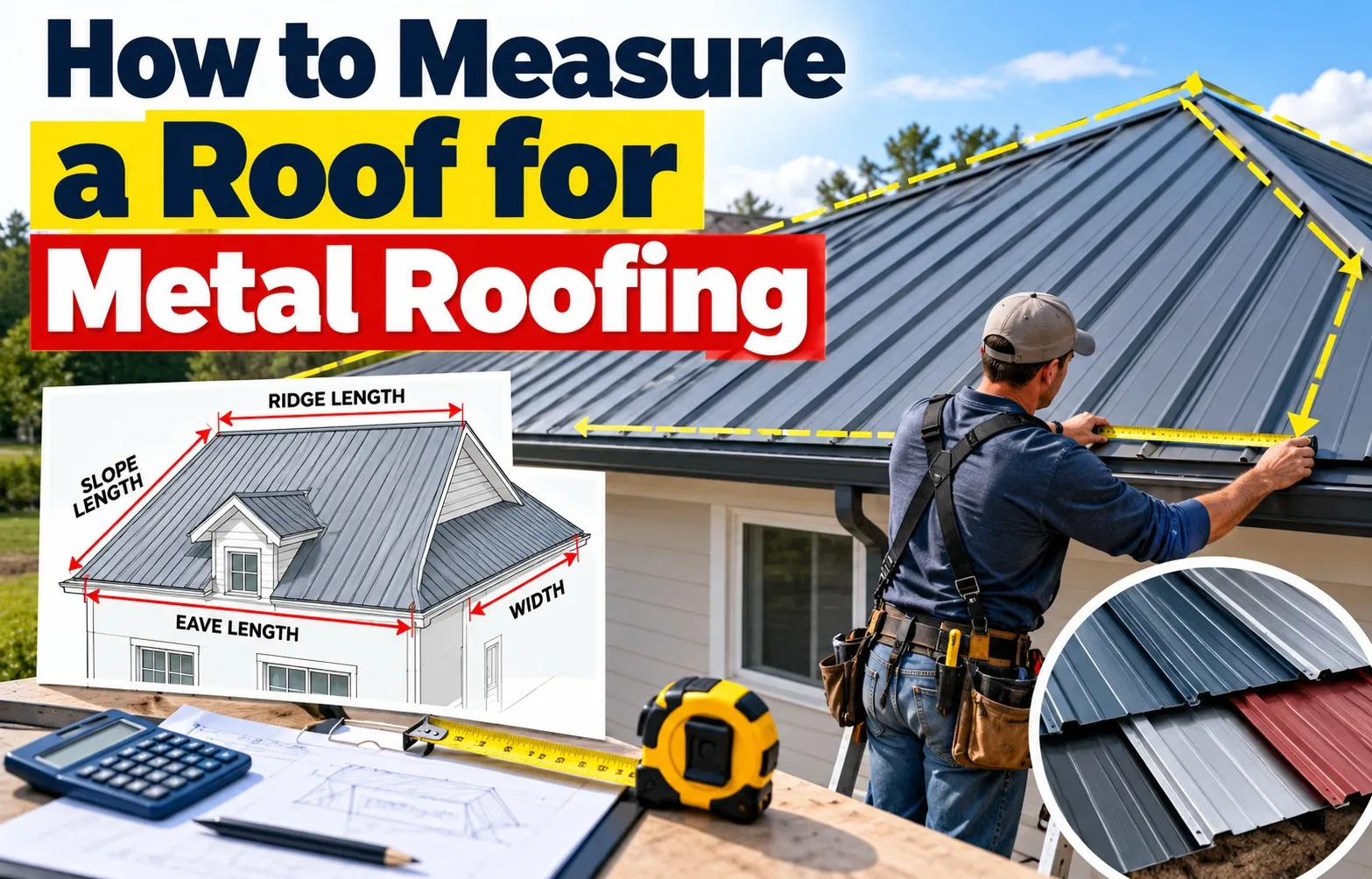 Measuring a metal roof requires linear panel calculations rather than basic area square footage. Metal panels are manufactured in fixed coverage widths, meaning you must determine the total width of each roof plane along the eave and divide it by the effective width of your selected panel profile.
Formula Cheat Sheet (The 30-Second Takeoff)
Unlike asphalt shingles sold by the square, metal roof materials are ordered by individual panel counts and linear trim feet. Calculate your base requirements using these standardized material estimation formulas:
- Total Panel Count Formula: Total Panel Count = Total Eave Width (in feet) / Panel Effective Coverage Width (in feet)
- Linear Feet of Trim Formula: Total Trim Pieces = Total Length of Edges (in feet) / Standard Piece Length (typically 10 feet)
- Overhang Adjustment Factor: Add 1 to 2 inches to eave-to-ridge slope measurements to allow proper water runoff into gutters.
For additional details on professional measurement standards, consult the Tri-County Metals Measurement Guide.
Essential Tools for Accurate Rooftop Takeoffs
Having the correct measuring and safety equipment ensures accurate material orders and prevents dangerous miscalculations during field measurements. Gather these tools before beginning your takeoff:
- 100 ft Steel Tape Measure: Standard cloth tape measures stretch over long distances, leading to inaccurate slope readings. Steel tape maintains tension across extended roof planes.
- Digital Pitch Locator / Angle Finder: Placed directly on the roof rafter or slope to measure the exact rise-over-run pitch ratio.
- Grid Notebook or Graph Paper: Used to sketch a scaled bird’s-eye roof takeoff outline and record every plane dimension.
- Chalk Line: Essential for checking the squareness of eave-to-ridge edges across wide spans.
- Digital Micrometer: Verifies panel steel thickness (e.g., 29-gauge vs. 26-gauge) when replacing existing metal sections.
- OSHA-Approved Safety Harness & Non-Slip Footwear: Required protection when measuring sloped surfaces directly.
Ground-Level vs. Rooftop Measuring: Safety First
Ground-level measurements using aerial elevation tools or tape measurements along fascia lines provide a fast starting point for simple gable roofs. However, stepping onto the roof is necessary whenever complex hips, valleys, sidewall flashings, or uneven dormers are present.
Always perform pitch readings and check eave squareness directly on the roof structure when safe to do so. On steep-sloped planes exceeding 6:12 pitch, utilize a pitch gauge from an extension ladder or use aerial imagery to maintain rooftop safety.
Drawing a Precision Roof Sketch & Mapping Structural Lines
Creating an accurate roof plan before ordering materials prevents costly sizing errors and shorted metal panel counts. A clear bird’s-eye sketch serves as your master blueprint for tracking every individual roof plane and transition.
Creating Your Bird’s-Eye Outline (Plane by Plane)
Start your roof plan by drawing an overhead footprint of the structure on graph paper. Break down complex roofs into individual rectangular or triangular geometric sections to simplify your linear math.
- Eaves: Mark the bottom horizontal edges where gutters attach and metal panels overhang.
- Ridges: Identify the highest horizontal peaks where opposing roof slopes intersect.
- Rakes / Gables: Outline the sloped side edges forming triangular gable ends.
- Valleys: Map the inside corners where two declining roof planes meet and channel heavy water flow.
- Hips: Note the outside sloped corners where two adjacent roof planes angle upward to a ridge.
Mapping Roof Penetrations and Transitions
Every obstruction interrupting a roof plane requires custom flashing and localized cutting. Accurately plotting these features on your bird’s-eye sketch ensures you order enough trim accessories and underlayment.
Mark the precise location and dimensions of chimneys, plumbing vent boots, and skylight flashing on your drawing. Additionally, record sidewalls and headwalls where the metal roof slope intersects vertical building walls or secondary structures.
Measuring Panel Lengths (Eave-to-Ridge Real-World Math)
Calculating correct metal panel lengths requires precise measurement along the actual roof slope rather than relying on ground dimensions. Precise eave-to-ridge panel length calculations ensure custom-cut metal sheets fit properly from peak to gutter.
Measuring Eave-to-Ridge Slope Distances
To measure slope length, hook a steel tape measure securely over the bottom edge of the fascia board or eave drip edge. Pull the tape straight up the sloped surface to the center line of the top ridge peak, ensuring the tape remains completely flat against the deck without sagging.
Measure every roof plane at three distinct points: near the left rake edge, at the center, and along the right rake edge. Record the longest measurement to ensure full coverage across uneven roof framing.
Essential Length Adjustments: Overhangs & Ridge Vent Gaps
Raw slope dimensions must be adjusted before placing factory custom-length panel orders. Account for gutter clearance and ridge ventilation gaps using these rules:
- Adding Overhang: Add 1 to 2 inches past the fascia board to allow water runoff to discharge cleanly into gutters without wicking back onto the fascia.
- Deducting for Vented Ridge Caps: Subtract 1 to 2 inches from the top peak to maintain the necessary air gap clearance required for continuous ridge vent airflow.
Checking Roof Squareness (3-4-5 Triangle Rule)
Unsquare framing causes rigid metal panels to run off alignment along the eave line. Use the geometric 3-4-5 triangle rule before ordering to verify whether your roof corners form true 90-degree right angles.
Measure 3 feet horizontally along the eave edge from a corner and mark the point. Next, measure 4 feet straight up the slope along the rake edge and mark that point. Measure the diagonal distance between both marks: if the diagonal equals exactly 5 feet, the corner is square; if not, your final panel lengths must accommodate the variance.
Calculating Panel Widths & Total Sheet Count
Converting horizontal roof measurements into exact sheet counts requires understanding the difference between a panel’s total manufactured width and its actual effective coverage width. Panel overlap and locking mechanisms reduce the usable surface area of every sheet.
Exposed Fastener Panels (36-Inch Effective Coverage)
Standard corrugated and ribbed roofing systems, such as AG-panels and Ultra-Rib profiles, feature exposed fastener designs where screws drive directly through the face of the metal. These panels typically have an actual manufactured width of 38 inches, but side-lap overlapping reduces their net panel coverage width to exactly 36 inches (3 feet).
To calculate your sheet quantity, divide the total horizontal eave length by the net coverage width. For example, if your total eave width measures 36 feet:
- Calculation Formula: 36 ft total eave width / 3 ft effective coverage width = 12 full panels required.
Standing Seam Panels (16-Inch to 24-Inch Coverage)
Concealed fastener systems, such as snap-lock or mechanical lock standing seam profiles, offer a cleaner architectural look with hidden clips. Because of their interlocking vertical rib profile, standing seam panels provide narrower effective coverage widths—typically ranging between 16 inches and 24 inches depending on the manufacturer.
Always verify the exact effective coverage width in your manufacturer specification sheets before dividing your eave measurements, as a 16-inch profile requires significantly more individual panels than a 24-inch profile for the same roof span.
Always Rounding Up and Panel Overlap Allowances
Roof measurements rarely result in clean whole numbers when divided by panel coverage widths. You must always round fractional calculations up to the next full panel integer to prevent shorting your material order.
Never trim down a panel to make up for a fraction unless absolutely necessary at gable edges. Ordering whole panels guarantees you maintain proper side-lap sealing and structural integrity across every roof plane.
Pitch Multipliers & True Surface Area Conversion
Flat ground measurements or two-dimensional aerial footprints do not account for the steepness of a roof slope. Converting flat plane measurements into accurate sloped panel surface area requires applying pitch multipliers based on your roof’s rise-over-run ratio.
How to Find Your Roof Pitch (Rise Over Run)
Roof pitch represents the vertical rise in inches for every 12 inches of horizontal run. To calculate your pitch, place a standard 12-inch carpenter’s level horizontally against the underside of an exposed rafter inside the attic or under the eave rakes, holding one end level against the slope.
Measure vertically from the 12-inch mark on the level straight up to the underside of the roof deck. If the vertical distance measures 4 inches, your pitch slope is 4:12; if it measures 6 inches, your pitch slope is 6:12.
Roof Pitch Multiplier Reference Table
Use this standardized pitch multiplier table to quickly convert flat ground or blueprint square footage into sloped surface area:
Converting Flat Area to Sloped Panel Area
To perform a surface area conversion, multiply your flat footprint area by the corresponding pitch multiplier factor. For example, if a house footprint measures 1,000 square feet with a 6:12 roof pitch:
- Calculation Example: 1,000 sq ft (flat area) x 1.118 (multiplier factor) = 1,118 sq ft actual sloped surface area.
Trim Flashing and Accessory Takeoff
Calculating trim components accurately is essential to completing a metal roofing takeoff without missing crucial weatherproofing accessories. Unlike custom-cut roof panels, metal trim and flashings are manufactured in standard fixed lengths, requiring specific lap allowances for continuous moisture protection.
Linear Trim Calculation Rules (10-Foot Standard Lengths)
Factory metal trim pieces are typically supplied in uniform 10-foot lengths. When joining two trim pieces along an edge, you must overlap them by 2 to 4 inches to prevent wind-driven rain penetration, which reduces the effective coverage of each piece to approximately 9.5 linear feet.
To determine the total number of trim pieces required for any line, take the total measured linear footage and divide it by 9.5 feet. Always round up your final calculation to the nearest whole piece to avoid ending up short on installation day.
Essential Trim Breakdown
Break down your roof sketch measurements into individual linear runs to calculate piece counts for every trim profile:
- Drip Edge / Eave Trim: Total linear feet along all eave lines / 9.5 feet. Installed under panels along eaves to direct water cleanly into gutters.
- Ridge Cap: Total linear feet along peak ridges / 9.5 feet. Covers top panel intersections while permitting ridge venting beneath.
- Gable / Rake Trim: Total linear feet along sloped rake edges / 9.5 feet. Seals panel edges along gable ends against wind uplift.
- Valley Flashing: Total linear feet along internal roof valleys / 9.5 feet. Channels heavy runoff where two roof slopes converge.
Estimating Fasteners Underlayment and Sealants
Accurate material orders require estimating hardware and underlayment materials based on total roof square footage. Order panel fasteners featuring neoprene washers at a rate of 80 to 100 screws per square (100 square feet) of roof area to ensure adequate spacing along rib profiles and purlins.
For underlayment, divide total sloped square footage by the coverage area listed on synthetic underlayment rolls (typically 1,000 square feet per roll), adding 10% for lap overlaps. Include rolls of butyl tape sealants for all trim joints, valley channels, and wall flashing transitions.</p
The Metal Roofing Waste Factor Matrix
Accounting for material scrap during metal roof measurements prevents shorted shipments and job site delays. Unlike asphalt shingles, which can be easily repurposed into starter strips, angled cuts on metal panels across hips, valleys, and dormers create unusable scrap that must be offset with a structured waste factor percentage.
Recommended Waste Percentages by Roof Type
Select your waste factor multiplier based on your specific roof geometry and architectural complexity:
Avoiding Common Ordering Pitfalls
When calculating final ordering overage for complex hip cuts and valley intersections, always remember that diagonal offcuts usually cannot be flipped over to fit the opposing side due to factory paint coatings and rib directionality. Factor in full panel lengths across all angled runs.
Always retain 1 to 2 spare full-length panels and extra trim pieces in storage after completing installation. Having matching factory batch metal on hand ensures seamless replacement panels during future weather repairs without experiencing lot-to-lot color variations.
Substructure & Installation Prep
Preparing the underlying framing and deck prior to panel installation ensures structural integrity and prevents long-term moisture damage. Understanding deck types, framing spans, and underlayment requirements completes your comprehensive roof measurement workflow.
Can You Install Metal Roofing Directly Over Plywood or Shingles?
Metal roofing can be installed directly over solid decking like plywood or OSB, and in many regions, directly over existing asphalt shingles if local building codes permit. Solid plywood decking provides a continuous, rigid surface that supports both exposed fastener and concealed fastener standing seam systems safely.
When installing over old shingles, inspect the roof surface for high spots, protruding nails, or rot. Shingle retrofits often require leveling underlayment or furring strips to prevent panel distortion.
Purlin Spacing Requirements (2×4 Framed Substructure)
When mounting metal roof panels on an open-framing system rather than a solid deck, proper purlin spacing prevents panel deflection under snow loads or wind uplift. For standard residential exposed fastener panels, 2×4 wood purlins are typically installed flat or on-edge at 24 inches on-center.
Heavier commercial or agricultural panel profiles can span up to 4 feet between supports depending on steel thickness and local structural engineering guidelines. Always consult your specific manufacturer load tables before spacing your framing members.
Moisture Barriers, Air Gaps, and Underlayment Options
Controlling attic and deck condensation is critical because metal panels rapidly fluctuate in temperature, causing underside moisture accumulation. Traditional asphalt-saturated felt tar paper degrades prematurely under prolonged metal heat contact, making high-temperature synthetic underlayment the superior industry standard.
Incorporating a synthetic moisture barrier combined with an air gap ventilation layer prevents trapped condensation from rotting roof decking. Ensure your underlayment is rated for high-temperature metal exposure before final installation.
Material Selection: 29-Gauge vs. 26-Gauge Metal
Selecting the correct steel gauge thickness determines your roof’s resistance to hail impact, wind uplift, and foot traffic denting. A 29-gauge metal roof is a popular, cost-effective choice for residential homes, offering adequate structural strength for standard pitches and mild weather zones.
Upgrading to a heavier 26-gauge or 24-gauge panel significantly increases rigidity, hail protection, and fastener holding power. Thicker panels are strongly recommended in areas prone to severe storms or heavy winter snow loads.
Frequently Asked Questions
Find direct answers to common questions regarding metal roof measurements, building codes, and underlayment selection to help secure featured snippet rankings.
What is the 25% rule in roofing?
The 25 rule roofing building code requirement dictates that if more than 25 percent of a roof’s total surface area is damaged or repaired within a consecutive 12-month period, municipal building codes typically mandate a full roof replacement rather than allowing a partial patch.
How do I measure a roof for metal panels without climbing onto it?
You can accurately measure a roof without climbing onto it by using aerial roof measurement software, digital pitch finder smartphone apps, or ground-level eave measurements combined with pitch multipliers. This approach captures true sloped dimensions safely from the ground.
Do I need tar paper or synthetic underlayment under a metal roof?
Traditional tar paper under a metal roof degrades prematurely under intense panel heat. Modern synthetic underlayment is essential because it withstands high thermal temperatures, prevents moisture condensation, and provides a durable, non-slip waterproof deck barrier.
How do you measure metal roof panels around valleys and hips?
For complex hip measurement and valley cuts, measure the longest point of the sloped panel run from the ridge down to the eave. Always order full rectangular panels and perform diagonal angle field-cuts on-site to ensure correct side-lap alignment.

Oscar Vance | Master Plumber & Drainage Expert
Meet Oscar Vance, a licensed master plumber sharing practical solutions on residential repairs, preventive maintenance, and thoughtful home upkeep.