Critical Pre-Installation Assessment & Safety Protocol
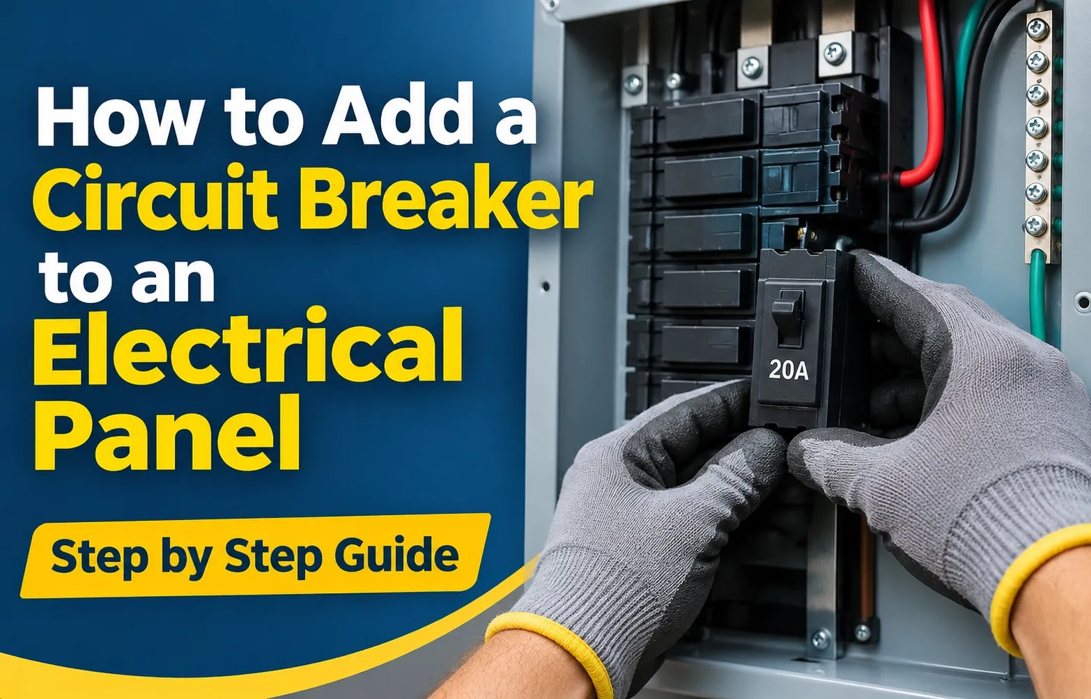 Installing a new circuit breaker requires working directly inside a main electrical panel where lethal voltage is present. Even when the main disconnect switch is toggled to the off position, severe electrocution risks remain inside the service box. You must evaluate safety requirements, local electrical codes, and your panel’s physical status before handling any tools.
Understanding Live Service Terminals vs. Main Breakers
Shutting off the main circuit breaker cuts power to the individual branch circuits, but it does not de-energize the entire panel. The main service lugs—the heavy gauge wires feeding directly from the utility meter into the top of the panel—remain energized with high amperage electricity at all times.
To safely evaluate the panel environment before beginning work, adhere strictly to these critical isolation protocols:
- Identify Always-Live Components: The incoming utility lines, main line lugs, and service entry cables are continuously energized unless the utility company physically pulls your meter or disconnects service at the pole.
- Verify Zero Voltage: Never trust a breaker label. Test every exposed terminal and wire using a reliable non-contact voltage tester or a digital multimeter calibrated for residential voltage before touching any metal component.
- Wear Approved PPE: Protect yourself against electrical arc flash hazards by using insulated personal protective equipment (PPE), including voltage-rated rubber gloves with leather protectors and ANSI-approved safety eyewear.
- Use Insulated Hand Tools: Work exclusively with VDE-certified or 1000V insulated hand tools to prevent accidental short circuits between live conductors and the grounded metal enclosure.
If you are uncomfortable navigating live service terminals, stop immediately and consult a licensed electrician to handle the installation.
Pre-Work Feasibility: Local Codes, Permits, and NEC Compliance
Adding a new circuit branch constitutes a permanent modification to your home’s electrical infrastructure. All work must comply with the Electrical Safety Foundation International (ESFI) safety standards and the governing edition of the National Electrical Code (NEC) enforced in your jurisdiction.
Review the following compliance and permitting factors prior to purchasing materials or running wire:
- Permit Requirements: Most municipal building departments mandate an electrical permit and a post-installation inspection when adding a new circuit to ensure system safety and preserve home insurance coverage.
- Arc-Fault & Ground-Fault Mandates: Modern NEC rules require Arc-Fault Circuit Interrupter (AFCI) protection for nearly all residential living areas, alongside Ground-Fault Circuit Interrupter (GFCI) protection for kitchens, bathrooms, basements, and outdoor circuits.
- Local Utility and Code Variations: Certain regions enforce local amendments that supersede national guidelines, such as prohibiting specific breaker panel modifications or restricting DIY electrical work entirely.
Panel Capacity Check: What to Do If Your Electrical Panel is Full
Opening your main service box only to find every physical slot occupied is a common obstacle. Before adding a new circuit, you must verify both the electrical load capacity of your system and the physical configuration options available within a full breaker box.
Calculating Remaining Panel Capacity and Electrical Load
Physical space inside an electrical panel does not guarantee available power reserve. Adding a new circuit to an overloaded panel can cause frequent nuisance trips, voltage drops, or thermal damage to the main bus bars.
Perform a basic load calculation and capacity check using the following criteria:
- Check Main Bus Bar Rating: Locate the panel door directory or interior label to find the panel capacity rating (typically 100-amp, 150-amp, or 200-amp).
- Calculate Existing Amperage Demand: Sum the continuous loads (lights, standard receptacles) and non-continuous large appliance loads (HVAC, water heater, dryer). Under standard NEC calculation guidelines, your total continuous load should not exceed 80% of the main panel capacity rating.
- Evaluate Current Slot Usage: Count the physical single-pole vs. dual-pole slots currently installed. Double-pole breakers occupy two physical slots and feed 240-volt appliances, while single-pole breakers occupy one slot for 120-volt circuits.
Tandem/Twin Breakers vs. Sub-Panel Installation: Choosing the Right Workaround
When all physical knockout slots are occupied, you have two primary code-compliant methods to expand circuit availability: installing tandem breakers or adding a feeder sub-panel.
To safely select between these options, follow these key implementation guidelines:
- Verify Tandem Breaker Compatibility: Inspect your panel schematic label. Panels designated as Class CTL will specifically identify which bus bar slots allow tandem breakers (often indicated by notched bus bar prongs). Never force a tandem breaker into a slot not listed for tandem use.
- Plan for a Sub-Panel: If your main panel does not accept tandem units or the total electrical demand exceeds panel capacity, install a secondary sub-panel. This involves running heavy-gauge feeder wire from a new double-pole breaker in the main box to a sub-panel enclosure, providing dedicated space for future circuit expansion.
Essential Tools, Materials & Compatibility Guide
Completing a safe and code-compliant installation requires specialized tools calibrated for electrical precision and components explicitly rated for your specific breaker panel. Using mismatched hardware or improvised tools poses immediate fire and electrical shock hazards.
The Non-Negotiable Tool Checklist (Safety Testers & Torque Tools)
Working inside a panel requires precise measuring instruments to verify power isolation and secure wire terminations to exact manufacturer specifications.
Gather the following required tools and materials before opening the service enclosure:
- Non-Contact Voltage Tester: Essential for checking outer wire insulation and open terminals for active voltage before physically touching components.
- Digital Multimeter: Used to measure exact AC voltage levels across bus bars, main lugs, and branch wires to confirm full power isolation.
- Torque Screwdriver (Calibrated in Inch-Pounds): Mandatory for tightening breaker terminal screws to exact manufacturer torque ratings stamped on the breaker label. Loose connections create resistance and dangerous heat buildup.
- Insulated Screwdrivers & Lineman’s Pliers: VDE-rated 1000V hand tools for safely manipulating wires and removing panel cover screws.
- Wire Strippers & Cable Cutters: For cleanly removing outer NM cable sheathing and stripping individual conductor ends without nicking the copper core.
- Strain-Relief Cable Clamps: Metal or plastic NM cable connectors to secure Romex wire where it passes through panel knockout holes, protecting the insulation from sharp metal edges.
Panel-to-Breaker Brand Compatibility Matrix (Square D, Siemens, Eaton, GE)
Circuit breakers are not universally interchangeable. Installing a breaker brand that is not explicitly listed on your panel door wiring diagram violates National Electrical Code standards, voids the manufacturer warranty, and invalidates UL-listed classification safety ratings.
Follow these verification steps when selecting your replacement breaker:
- Locate the Panel Information Label: Open the metal door of your electrical panel and read the manufacturer label listing approved breaker types.
- Match Mounting Styles: Ensure you purchase the correct attachment style (plug-in vs. bolt-on). Most residential load centers use plug-in style bus bar attachments.
- Check UL Classification: Only use breakers explicitly labeled as UL-Listed for your specific load center model to ensure safe mechanical bus bar contact.
Wire Sizing & Ampacity Master Reference Guide
Selecting the correct wire gauge and matching it accurately to the circuit breaker amperage is vital for preventing conductor overheating and electrical fires. Undersized wire paired with an oversized breaker creates an extreme fire hazard because the cable will overheat and melt before the circuit breaker trips.
Matching Wire Gauge to Circuit Amperage (15-Amp vs. 20-Amp vs. 30-Amp)
Conductor ampacity ratings dictate the maximum electrical current a wire can carry continuously without exceeding its rated thermal threshold. You must always align your copper wire gauge directly with the protective rating of the circuit breaker.
Adhere strictly to these foundational wire sizing safety rules:
- Never Downsize Wire for a Larger Breaker: You can never install 14-gauge wire on a 20-amp breaker, as the higher current flow will exceed the wire ampacity limit.
- Upsizing is Permissible: You can safely install thicker wire on a smaller breaker (such as 12-gauge wire on a 15-amp breaker), though it is more rigid to route.
- Verify Copper Composition: Ensure all residential branch wiring uses solid or stranded copper conductors rated for interior residential use.
Wire Run Distance, Voltage Drop, and Conductive Capacity Limits
Long electrical wire runs experience internal resistance that results in voltage drop, causing connected appliances to underperform or overheat. Calculating wire gauge ampacity requires factoring total run distance from the main panel to the final device location.
Keep these critical distance and resistance parameters in mind during planning:
- NEC Voltage Drop Guidelines: The National Electrical Code recommends keeping branch circuit voltage drop below 3% to ensure efficient appliance operation and prevent electronic faults.
- Distance Thresholds for 12/2 Wire: On a standard 20-amp circuit using 12/2 NM-B wire, runs exceeding 75 to 100 feet often require stepping up to 10-gauge wire to offset resistance losses.
- Compounding Thermal Load: Extended distance multiplies total loop resistance, increasing thermal energy generation along the entire length of the hidden cable run.
How to Install a Circuit Breaker
Executing a safe circuit breaker installation requires following a strict chronological sequence from power isolation to final system testing. Performing these steps methodically ensures full code compliance, protects delicate components, and eliminates electrocution hazards.
Step 1: Shutting Off Main Power and Verifying Zero Voltage
Turn off the main service feed before touching any internal panel components. Use a reliable digital multimeter or non-contact tester to complete zero-voltage verification across all branch terminals and bus bars.
- Locate the Main Disconnect Toggle: Flip the large 100A to 200A main breaker handle to the off position to cut power to all individual branch circuits.
- Test for Residual Voltage: Touch your tester probes to various breaker screws to confirm that downstream power is completely absent.
- Acknowledge Live Lugs: Keep in mind that incoming service entry wires at the top of the panel remain continuously energized.
Step 2: Removing Panel Cover and Knocking Out Entry Slots
Unscrew the metal panel cover safely from bottom to top while supporting its weight. Use pliers and a flathead screwdriver to pop out a clean knockout plug for your new cable entry.
- Support Cover Weight: Keep a firm grip on the heavy steel cover so it does not drop against internal live lugs when the final screws are removed.
- Remove Metal Knockout: Tap the selected knockout tab inward with a screwdriver and twist it completely free with lineman’s pliers to create an open port.
- Inspect Edges: Ensure no sharp metal burrs remain around the port that could puncture wire insulation during installation.
Step 3: Feeding and Securing Romex Cable with Strain-Relief Clamps
Secure your incoming NM-B cable through an approved strain-relief clamp installed in the knockout hole. Leave at least a quarter-inch of outer plastic sheathing visible inside the metal enclosure.
- Install Cable Clamp: Insert a listed metal or plastic clamp into the knockout hole and tighten its locking nut securely from the inside.
- Feed Cable Correctly: Push three to four feet of Romex cable through the clamp, ensuring the outer plastic jacket extends past the clamp throat.
- Protect Conductor Integrity: Tighten the clamp screws just enough to hold the cable firmly without crushing the internal conductors.
Step 4: Routing Ground & Neutral Wires (Standard vs. AFCI/GFCI Pigtails)
Terminate bare ground wires directly to the ground bus bar. Route neutral wires to the neutral bus bar or connect specialized AFCI/GFCI pigtails to their designated breaker terminals.
- Ground Wire Connection: Strip the outer jacket back, gather the bare copper ground wire, and clamp it tightly into an open terminal on the ground bus bar.
- Standard Neutral Routing: For standard breakers, strip a half-inch of white neutral wire insulation and secure it directly to the neutral bus bar.
- AFCI/GFCI Pigtail Setup: For advanced breakers, attach the white circuit wire to the breaker’s neutral terminal, then connect the pre-attached curly white pigtail wire to the neutral bus bar.
Step 5: Connecting the Hot Wire and Torquing Terminal Screws
Strip a half-inch of insulation from the black conductor hot wire and insert it firmly into the breaker terminal slot. Tighten the lug screw precisely to the manufacturer’s specified inch-pound torque spec.
- Strip Conductor Cleanly: Use wire strippers to expose solid copper without nicking or scoring the metal strand.
- Insert into Terminal Slot: Push the bare copper end completely into the breaker’s lug opening until no exposed wire remains outside the housing.
- Apply Exact Torque Spec: Use a calibrated torque screwdriver to tighten the terminal screw to the exact inch-pound torque spec stamped on the side of the breaker.
Step 6: Snapping the Breaker onto the Bus Bar & Panel Reassembly
Hook the rear notch of the toggled-off breaker onto the mounting rail and press firmly until the bus bar prong clip locks in place. Reinstall the panel cover and restore power carefully.
- Toggle Breaker Off: Ensure the new breaker handle is in the OFF position before attempting physical mounting.
- Engage Bus Bar Prong Clip: Hook the back edge onto the mounting rail and snap the front forward until the spring clip clamps tightly onto the metal bus bar.
- Reinstall Cover and Test: Fasten the steel panel cover back into place, turn the main breaker back on, and toggle your new branch breaker to test functionality.
Testing, Troubleshooting, and Circuit Mapping
Validate your completed installation by testing advanced safety mechanisms, diagnosing potential faults, and updating the physical panel directory. Rigorous post-installation testing ensures that AFCI and GFCI protection systems function properly while preventing hidden wiring errors from creating hazardous conditions.
Testing AFCI GFCI Trip Functions and Mechanical Reset
Verify advanced circuit protection immediately after restoring power by executing manual trip tests. Pressing the built-in test button forces an artificial electrical imbalance to confirm that the internal electronics will successfully interrupt current flow during a real emergency.
- Engage Main Power: Turn the main breaker and the newly installed branch circuit breaker to the ON position after completing the assembly.
- Press the AFCI Test Button: Locate the dedicated test button on the face of the breaker and press it firmly; the handle should instantly snap to the tripped position or center neutral indicator.
- Execute Mechanical Reset: Toggle the breaker handle fully to the OFF position to reset the internal mechanical latch, then flip it back to the ON position.
Troubleshooting Immediate Breaker Trips and Neutral Faults
Diagnose immediate breaker trips or continuous fault codes by isolating wiring errors and neutral cross-connections. If the breaker trips instantly upon being switched on, you are dealing with a direct short circuit or a compromised conductor contacting a grounded metal surface.
- Identify Short Circuits: An instant, forceful trip usually indicates a crossed hot wire touching a grounded metal box or an uninsulated bare copper wire contacting a hot terminal.
- Check for Ground Faults: Sensitive breakers utilize ground fault detection to monitor current balance, tripping instantly if electricity leaks outside the intended loop.
- Inspect Neutral Pigtails: Ensure that advanced AFCI/GFCI white neutral pigtails are securely connected directly to the neutral bus bar rather than shared incorrectly with other circuits, which triggers false trip codes.
Updating the Panel Directory and Circuit Mapping
Document your new circuit clearly on the physical panel directory map to ensure long-term safety and code compliance. An accurate circuit mapping log prevents confusion during future home maintenance and fulfills standard residential electrical codes.
- Map Connected Zones: Walk through your home and test every outlet, switch, or appliance connected to the new line to confirm its exact boundaries.
- Update the Panel Directory Map: Write the specific room name, appliance type, or zone description legibly on the corresponding breaker slot number inside the panel door.
- Apply Permanent Labels: Avoid fading pencil markings or temporary tape; use a permanent marker or printed label maker strip to maintain clear legibility for years to come.
Frequently Asked Questions
Addressing specific code rules, load capacity limits, and installation costs helps prevent common DIY mistakes. Below are authoritative answers to high-volume technical questions regarding branch circuit breaker installations.
Can I put a 30-amp breaker in place of a 20-amp breaker?
No, you cannot replace a 20-amp breaker with a 30-amp breaker unless the existing circuit wiring is rated to handle 30 amps of continuous electrical current. Circuit breakers provide overcurrent protection designed to disconnect power before the conductor wire reaches dangerous temperatures.
- Severe Fire Risk: Installing a 30-amp breaker on 12-gauge wiring creates a fire risk because the wire will overheat and melt long before the 30-amp breaker trips.
- Proper Procedure: If an existing 20-amp breaker trips frequently, calculate the connected electrical load or pull a larger conductor wire (such as 10-gauge copper wire) before increasing breaker capacity.
Can you run 14-2 wire on a 20-amp breaker?
No, you cannot connect 14-2 wire to a 20-amp breaker. Under standard National Electrical Code guidelines, 14-gauge copper wire has a maximum ampacity rating of 15 amps.
- 14-Gauge Wire Limits: Using 14-gauge wire on a 20-amp circuit violates building codes because the wire insulation can break down under a 20-amp load without tripping the breaker.
- Correct Matching: Always use 12-gauge copper wire (12/2 NM-B) for a 20-amp circuit, or downsize your circuit breaker to 15 amps if using 14-gauge wire.
How many outlets or sockets can I run on a 20-amp breaker?
While the National Electrical Code does not set a strict hard limit for residential general-purpose outlets on a single branch circuit, standard industry practice recommends installing a maximum of 10 to 12 outlets on a 20-amp circuit.
- Continuous Load Rule: A 20-amp circuit provides 2,400 watts of total capacity at 120 volts, but continuous operating loads should not exceed 80% of rated capacity (1,920 watts).
- Outlet Load Limits: Divide high-draw devices (such as space heaters or microwave ovens) across multiple circuits rather than crowding them onto a single 20-amp line.
Can I run a refrigerator and general outlets on the same 20-amp circuit?
While code permits a refrigerator to share a general-purpose 20-amp circuit in certain areas, electrical standards strongly recommend a refrigerator dedicated circuit to protect food storage from nuisance trips.
- Prevent Nuisance Trips: Sharing a refrigerator line with general outlets increases the risk that an overloaded receptacle or shorted lamp will trip the breaker, turning off power to the appliance unnoticed.
- Compressor Inrush Current: Refrigerator compressors draw significant inrush current during startup, which can cause lights to flicker or trip sensitive AFCI breakers if shared with other devices.
How much does it cost to have an electrician add a circuit breaker?
Hiring a licensed electrician to install a standard single-pole circuit breaker typically costs between $150 and $350 total, including parts and labor. The price varies based on panel accessibility, geographic region, and breaker type.
- Electrician Labor Cost: Professional hourly rates for licensed electricians range from $75 to $150 per hour, with most single-breaker additions taking 1 to 2 hours to complete.
- Material Expenses: Standard 15A or 20A breakers cost $10 to $25, while specialized AFCI, GFCI, or dual-function breakers cost between $40 and $90 each.

Oscar Vance | Master Plumber & Drainage Expert
Meet Oscar Vance, a licensed master plumber sharing practical solutions on residential repairs, preventive maintenance, and thoughtful home upkeep.