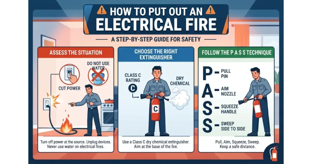
Critical Electrical Safety Warning & Emergency Precautions
 Working inside a main electrical panel exposes you to lethal voltages up to 240 volts and severe arc flash risks. Even when you switch the main breaker off, energized electrical conductors remain fully active inside the box. Prioritize personal safety by understanding energized components, equipping proper personal protective equipment (PPE), and recognizing when a job exceeds DIY limits.
The Always-Live Service Lugs: What Remains Dangerous After Shutting Off Power
Flipping the main breaker to the “Off” position disconnects power to all branch circuits, but it does NOT de-energize the entire panel. The incoming utility service wires and their connection terminals—known as service lugs—remain continuously live with direct current from the power company.
Contact with these live service lugs can cause fatal electrocution or trigger an electrical arc flash hazard. Always maintain strict physical clearance from the upper portion of the panel box.
- Utility Service Lugs: Located at the top of the main breaker assembly, these large aluminum or copper connectors stay continuously energized at 120/240 volts.
- Main Bus Bars (Upper Section): The metal contact points above the main disconnect switch remain live until the utility company physically pulls your meter.
- Arc Flash Risks: Accidental contact with a metal tool across live terminals can instantly create an explosive arc flash reaching thousands of degrees.
Mandatory Safety Equipment Checklist (PPE & Insulated Tools)
Working safely on electrical distribution equipment requires rated personal protective equipment and specialized non-conductive hand tools. Standard household tools lack electrical insulation and must never be used inside a service panel.
Inspect all protective gear for cracks, tears, or physical damage before opening the deadfront cover. Using unrated or damaged tools drastically increases electrocution risks.
- 1000V-Rated Insulated Screwdrivers: Hand tools certified under VDE/ASTM F1505 standards featuring dual-layer insulated shafts to prevent accidental grounding bridging.
- Non-Contact Voltage Tester: A functional, battery-checked voltage detector to verify zero electrical current on branch wires and terminal screws.
- ANSI-Approved Safety Glasses: High-impact eye protection to guard against flying debris or sparks in the event of an unexpected arc.
- Rubber-Soled Boots & Dry Footing: Dielectric footwear that insulates your body from ground potential. Never work on wet concrete or damp surfaces.
- Heavy-Duty Electrical Gloves: Leather or rubber insulating gloves rated for residential voltage handling.
When to Stop: Signs You Must Hire a Licensed Electrician Immediately
Certain panel conditions present severe danger and strictly require the intervention of a certified master electrician. Attempting DIY breaker replacement under hazardous panel conditions violates local building codes and risks structural fires.
If you observe any of the critical warning signs listed below, immediately secure the panel cover, leave the main power off if active arcing is present, and contact a professional.
- Corrosion or Rust on Bus Bars: White powder, rust, or greenish oxidation on the internal metal rails indicates water intrusion, leading to high-resistance connections.
- Visible Melted Insulation or Charring: Burn marks on existing breakers, scorched wire jackets, or black residue inside the panel box signal severe thermal damage.
- Obsolete or Recalled Panel Brands: Federal Pacific Electric (FPE) Stab-Lok, Zinsco, or Sylvania panels carry known failure rates and require complete panel replacement rather than simple breaker swaps.
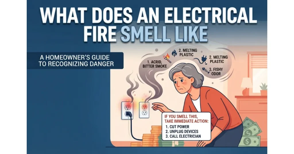
- Buzzing, Sizzling, or Burning Odors: Audible humming or fishy chemical smells indicate active arcing and impending component breakdown.
- Aluminum Branch Wiring: Legacy solid-aluminum wiring requires special anti-oxidant compound and specialized CO/ALR rated terminal torque protocols.
Essential Tools, Materials, & Panel Compatibility Matrix
Selecting the correct breaker model and securing accurate testing tools are non-negotiable pre-requisites before attempting any electrical panel modification. Installing an incompatible breaker onto a bus bar creates loose contact points, causing severe thermal arcing, melted insulation, and potential house fires. Adhering strictly to National Electrical Code (NEC) guidelines ensures your installation meets safety standards and maintains proper equipment listings.
Required Tools & Testing Instruments
Precise electrical measurements require functional, high-quality instruments calibrated for residential voltage levels. Never rely on visual inspection alone to determine if a circuit is dead.
Gather all necessary equipment before removing the deadfront panel cover to prevent leaving an energized or open electrical panel unattended.
- Digital Multimeter or CAT III Voltage Tester: Essential for taking precise AC voltage readings between hot terminals, neutral bars, and ground points.
- Non-Contact Voltage Detector (NCVT): Used for initial zero-voltage verification on insulated wire jackets before touching terminal screws.
- 1000V Insulated Screwdriver Set: Flathead and Phillips drivers rated to prevent accidental grounding if a tool slips near bus bar connections.
- Terminal Torque Wrench: Ensures terminal screws are tightened to manufacturer-specified inch-pound ratings to prevent loose wire arcing.
- Flashlight or Headlamp: Battery-powered lighting is mandatory since turning off the main disconnect cuts power to household lighting circuits.
Choosing the Right Replacement: OEM vs. UL-Classified Breakers
Electrical panel manufacturers design their bus bar connection points with proprietary clip profiles, rail heights, and stabbing mechanisms. Installing an incorrect breaker brand voids the Underwriters Laboratories (UL Listing) of the entire service panel.
Always check the manufacturer label inside your panel door to verify acceptable replacement brands and series codes before purchasing parts.
Breaker Type Identification (Single-Pole vs. Double-Pole vs. AFCI/GFCI)
Modern residential circuits rely on different breaker configurations depending on voltage demands, wire count, and local NFPA 70 code mandates. Replacing a breaker requires matching both physical size and internal safety mechanics.
Inspect the existing unit’s body and handle tie to identify its exact mechanical class and ampere rating (such as 15A, 20A, 30A, or 50A).
- Single-Pole Breakers (120V): Occupy one panel slot, feature a single handle, and connect to one hot bus bar prong. Typically rated for 15A or 20A branch circuits powering standard lighting and outlets.
- Double-Pole Breakers (240V): Occupy two adjacent panel slots, feature a tied double handle, and clamp onto two separate 120V bus bars. Rated for heavy loads such as 30A water heaters or 50A electric ranges.
- Arc Fault Circuit Interrupter (AFCI): Features advanced microprocessors to detect hazardous electrical arcing in branch wiring. Required by modern codes for living areas and bedrooms.
- Ground Fault Circuit Interrupter (GFCI): Monitors current balance between hot and neutral conductors, shutting off power within milliseconds if a ground fault occurs near moisture (kitchens, bathrooms, outdoor outlets).
How to Replace a Standard Circuit Breaker
Replacing a standard single-pole or double-pole circuit breaker requires methodical precision, exact tool handling, and rigorous adherence to safety procedures. By following a structured step-by-step workflow, you can successfully remove a faulty breaker and install a new replacement without compromising electrical safety. Review the video walkthrough below for a visual demonstration before beginning your project.
Step 1: Power Down the Branch Circuit & Main Electrical Service
Shutting off both the specific branch breaker and the main service disconnect stops electrical flow to the work zone. Never attempt to pull a breaker while power is actively running through that individual circuit.
Complete this initial shutdown sequence carefully to isolate the work area before removing any physical housing shields.
- Locate and Toggle Branch Breaker: Find the specific branch breaker connected to the faulty circuit and switch it firmly to the “Off” position.
- Disengage Main Service Disconnect: Locate the main breaker (typically positioned at the top or center of the panel) and switch it to “Off” to kill power to all downstream branch circuits.
- Confirm Auxiliary Switches: Ensure all individual breakers inside the panel box are toggled off to maintain complete electrical isolation during servicing.
Step 2: Safely Remove the Deadfront (Panel Cover Outer Plate)
Unfastening the deadfront panel cover requires supporting its weight to prevent dropping the heavy metal plate onto live service components. Always leave one corner screw for last while holding the cover securely.
Keep your tools organized and avoid letting metal fasteners slip into the open panel enclosure during removal.
- Unscrew Fastening Screws: Use an insulated screwdriver to remove the sheet metal screws securing the deadfront panel cover to the enclosure frame.
- Support Cover Weight: Support the metal plate with one hand while backing out the final remaining screw located at the upper corner.
- Lift and Set Aside: Carefully lift the deadfront panel cover straight off and store it away from your immediate workspace to maintain a clear line of sight.
Step 3: Perform Multi-Point Zero-Voltage Verification
Testing for voltage with a digital multimeter and non-contact voltage detector confirms zero electrical potential before touching internal panel components. Never assume a wire is safe without explicit multi-point verification.
Double-check your testing instruments before and after scanning the target conductor to ensure accurate diagnostic results.
- Test Detector Function: Check your non-contact voltage detector on a known live source or built-in test button to ensure the battery and sensor operate correctly.
- Scan Insulated Conductors: Sweep the voltage detector along the copper wire connected to your target breaker to verify absolute absence of current.
- Measure with Digital Multimeter: Set your digital multimeter to AC Volts, placing probes between the hot terminal screw of the target breaker and the neutral bus bar to confirm a reading of 0.0 volts.
Step 4: Disconnect Terminal Wires & Unclip the Old Breaker
Loosening the hot terminal screw and releasing the bus bar clip rail allows you to extract the faulty breaker safely. Take a reference photo of the wire placement before detaching any physical connections.
Pull straight outward with controlled force to prevent bending internal panel bus bar components.
- Loosen Terminal Screw: Turn the side terminal screw counter-clockwise using an insulated screwdriver and gently pull the copper wire free from the clamping jaws.
- Release Bus Bar Clip Rail: Grasp the inner edge of the breaker near the center bus bar and rock or pull it outward to disengage its mounting clip.
- Pivot and Remove: Pivot the outer edge away from the retaining rail to fully lift the old breaker out of the electrical enclosure.
Step 5: Seat and Secure the New Replacement Circuit Breaker
Snapping the new replacement circuit breaker onto the mounting rail and tightening the terminal screw to proper specifications ensures a secure, low-resistance connection. Ensure the replacement breaker is switched to the “Off” position before installation.
Verify that your replacement unit matches the exact brand, series, and ampere rating required by your panel manufacturer.
- Hook Onto Mounting Rail: Position the outer edge of the new breaker so it catches securely onto the mounting rail notch.
- Snap Into Bus Bar Clip Rail: Press the inner edge firmly onto the bus bar until you feel and hear a distinct click, then give it a gentle tug to confirm stability.
- Attach Copper Wire and Torque: Insert the stripped end of the copper wire under the hot terminal screw and tighten it down, adhering strictly to the manufacturer terminal torque spec to prevent loose contact arcing.
Step 6: Reinstall Panel Cover & Execute Power-Restoration Testing
Reattaching the deadfront panel cover and applying the step-aside power restoration protocol safely re-energizes your electrical system. Test downstream receptacles and lights to verify correct operation before declaring the project complete.
Stand clear of the enclosure faceplate while restoring main power as an added precaution against unexpected equipment faults.
- Reinstall Deadfront Cover: Position the deadfront panel cover back over the enclosure box and fasten all sheet metal screws securely.
- Apply Step-Aside Protocol: Stand physically to the side of the electrical panel and flip the main service disconnect breaker back to the “On” position.
- Restore and Test Circuits: Toggle individual branch circuit breakers back on one at a time, then test connected household lights or outlets using a plug-in circuit analyzer.
Advanced Wiring Guide: Replacing Modern AFCI & GFCI Breakers
Modern electrical codes mandated by NFPA 70 require Arc Fault Circuit Interrupter (AFCI) and Ground Fault Circuit Interrupter (GFCI) protection for most residential living spaces. Unlike standard single-pole breakers that only manage hot conductors, modern AFCI and GFCI breakers monitor neutral return paths and require specialized wiring connections like coiled neutral pigtails or plug-on neutral bus bars. Review the video walkthrough below for a detailed demonstration before beginning your installation.
Understanding Coiled Neutral Pigtails vs. Plug-on Neutral (PoN) Bars
Modern combination AFCI and GFCI breakers require a dedicated neutral connection to monitor current balance and detect hazardous arcing faults. Depending on your panel generation, you will either connect a flexible coiled neutral pigtail directly to the neutral bar or snap the breaker onto a specialized plug-on neutral (PoN) spring clip.
Properly managing neutral conductors prevents nuisance tripping and ensures compliance with current residential wiring standards.
- Coiled Neutral Pigtail: A factory-attached white or white-striped lead wire extending from the breaker body. This pigtail must be inserted and screwed into an open terminal port on the neutral/ground bar.
- Plug-on Neutral (PoN): Advanced panel design featuring a dedicated spring-loaded terminal clip on the back of the breaker that automatically mates with a specialized neutral bus bar rail, eliminating loose external pigtail wires.
- Equipment Ground Integration: While neutral conductors carry return current, equipment ground wires attach separately to the grounding bar to protect users from metallic chassis shocks.
Step-by-Step AFCI/GFCI Breaker Installation & Load Neutral Connection
Installing an AFCI or GFCI breaker requires managing both the standard hot wire and the circuit’s load neutral conductor. Failing to connect the circuit’s white neutral wire directly to the breaker’s dedicated load terminal will cause the unit to trip instantly upon power restoration.
Follow this precise wiring sequence to integrate modern safety breakers into your existing panel configuration.
- Connect Load Neutral Wire: Strip 3/8-inch of insulation from the circuit’s white neutral wire and secure it firmly into the breaker’s marked neutral terminal screw (often labeled “Panel Neutral” or indicated by a white square).
- Attach Pigtail (If Applicable): Route the breaker’s factory coiled neutral pigtail neatly along the edge of the panel box and secure it into an available screw slot on the neutral bar.
- Mount and Wire Hot Conductor: Snap the breaker onto the bus bar clip rail, insert the black hot wire into the hot terminal screw, and torque all connections to manufacturer specifications.
How to Test and Reset Self-Diagnostic AFCI/GFCI Breakers
Modern AFCI and GFCI breakers feature built-in microprocessors with self-diagnostic testing capabilities and LED trip indicator codes. After completing installation and restoring power, you must perform a manual test cycle using the onboard test button to verify that the internal sensor mechanism functions correctly.
Routine diagnostic testing ensures your circuit protection devices remain fully operational against electrical fires and shock hazards.
- Onboard Test Button: Press the physical “Test” button located on the face of the breaker while power is active. The breaker should trip immediately, throwing the handle to the center or tripped position.
- LED Trip Indicator Codes: Many modern AFCI breakers feature flashing LED lights that store historical trip data (such as arc-to-ground versus arc-to-neutral faults) to assist with advanced troubleshooting.
- Manual Reset Procedure: Push the breaker handle firmly past the “Off” position to fully reset the internal mechanical latch before flipping it back to the “On” position.
Critical Safety Analysis: Can You Upgrade Amperage (15A to 20A / 20A to 30A)?
Upgrading a circuit breaker’s amperage without upgrading the underlying wire gauge is a dangerous code violation that frequently causes in-wall electrical fires. An overcurrent protection device (OCPD) exists to protect the physical building wiring, not the appliances plugged into the circuit. Replacing a 15-amp breaker with a 20-amp or 30-amp breaker on existing undersized wire allows destructive levels of electrical current to flow through copper conductors that cannot handle the thermal load.
The Hidden Fire Hazard: Matching Wire Gauge (AWG) to Breaker Amperage
Circuit breakers protect the physical building wiring rather than individual connected devices. When you install an oversized breaker on thin copper wire, the conductor acts as a heating element before the breaker can trip. This mismatch causes severe wire insulation thermal melting behind drywall, creating a catastrophic in-wall fire hazard.
Understanding how electrical current generates heat within copper conductors is essential for preventing structural fires during home electrical modifications.
- Conductor Resistance: Thinner copper wires possess higher electrical resistance, converting excess electrical current directly into thermal energy instead of safely transmitting power.
- Premature Insulation Breakdown: As wire temperature exceeds safe thresholds, thermoplastic wire insulation degrades, cracks, and exposes bare metal conductors to framing timbers.
- Delayed Trip Response: An oversized breaker fails to register an overcurrent condition until the wire has already reached a dangerously high thermal state.
Wire Gauge Quick-Reference Chart (14 AWG vs. 12 AWG vs. 10 AWG)
American Wire Gauge (AWG) standards dictate strict ampacity limits for residential copper conductors based on cross-sectional area and thermal dissipation thresholds. Exceeding these current limits transforms standard house wires into dangerous heat sources. Review the compliance parameters below before selecting any breaker amperage.
Never substitute a higher-amperage breaker without physically verifying that the entire wire run matches the required gauge specification from the panel to the final outlet.
Why Increasing Breaker Size Without Rewiring Violates Electrical Code
National Electrical Code (NEC) regulations strictly prohibit installing a circuit breaker with a higher ampere rating than the ampacity of the attached circuit conductors. Bypassing this rule during a panel upgrade or breaker swap creates severe legal liability, invalidates homeowner insurance policies, and risks total structural loss.
Adhering strictly to wire ampacity limits protects both the integrity of your electrical system and the safety of your home’s occupants.
- Code Enforcement Violations: Unauthorized breaker size upgrades fail standard municipal electrical inspections and must be entirely reversed before selling a property.
- Insurance Claim Denial: Property insurance carriers routinely deny coverage for fire damage if investigation reveals unpermitted electrical modifications or oversized circuit protection.
- Fixture and Receptacle Incompatibility: Standard 15-amp outlets and switches are not rated to handle 20-amp or 30-amp continuous loads, leading to terminal melting at device connection points.
Troubleshooting & Diagnostic Matrix: Why Does a New Breaker Keep Tripping?
When a newly installed circuit breaker trips immediately upon power restoration or emits unusual panel noises, it points to an underlying wiring error, an existing load fault, or a compromised physical connection. Systematic troubleshooting is essential to identify whether the issue stems from the connected branch circuit or the panel bus bar itself.
Differentiating Circuit Overloads, Short Circuits, and Ground Faults
Pinpointing the exact cause of a tripped breaker requires understanding the three primary types of electrical faults. Each fault creates a distinct signature and demands a specific diagnostic approach before resetting the protection device.
Isolate the branch circuit wiring and examine connected appliances or fixtures to determine which condition is triggering the trip.
- Electrical Overload: Occurs when total current draw exceeds the breaker’s amp rating (e.g., running too many high-wattage appliances simultaneously). The breaker trips after internal thermal components heat up.
- Short Circuit to Ground: Happens when a frayed hot wire physically touches a grounded metal box or conduit, creating an immediate, massive surge of current that instantly snaps the breaker.
- Hot-to-Neutral Short: Caused by a direct fault where the ungrounded hot conductor contacts the neutral return path, bypassing normal resistance and causing an immediate short-circuit trip.
Inspecting the Panel Bus Bar for Pitting, Corrosion, or Heat Damage
If a new breaker trips instantly or you notice a buzzing panel during operation, the physical mounting interface inside the enclosure may be damaged. A worn bus bar prevents proper mechanical engagement and leads to dangerous electrical arcing.
Inspect the metal stab rail closely under bright lighting before inserting any replacement hardware.
- Bus Bar Pitting: Surface erosion and craters on the tin-plated copper rails caused by historical arcing or moisture exposure, which disrupts solid electrical contact.
- Thermal Arc Damage: Discoloration, black carbon deposits, or warped plastic separators signaling severe overheating from previous loose connections.
- Loose Jaw Clip Contact Resistance: When the spring-steel grip inside a breaker fails to clamp tightly onto the bus bar, high contact resistance generates localized heat and a buzzing panel sound.
What to Do If a Replacement Breaker Trips Immediately Upon Power Restoration
If a brand-new breaker trips the split second you flip it to the “On” position, do not force it to stay reset. This behavior confirms a permanent, hard short or a miswired neutral conductor within the branch circuit.
Execute a systematic isolation procedure to locate and resolve the fault safely.
- Disconnect Branch Load Wires: Remove the hot and neutral wires from the tripped breaker terminal, reset the handle, and turn the breaker back on to rule out a defective internal breaker mechanism.
- Multimeter Continuity Testing: Use digital multimeter continuity testing with the main power off to check for unintended paths between the hot conductor and grounded metal framing.
- Isolate Downstream Devices: Unplug all lamps, appliances, and electronic devices on that branch circuit one by one to check if a failed appliance is causing the fault.
Cost Breakdown & Panel Longevity: DIY vs. Electrician & Panel Replacement Signs
Replacing a circuit breaker costs between $10 and $50 for parts if performed yourself, compared to $150 to $350 when hiring a licensed professional. Evaluating financial expenses alongside the structural age and physical condition of your electrical equipment ensures you choose between a safe component swap and a necessary full panel upgrade.
DIY Breaker Replacement Cost vs. Professional Electrician Service Fees
Understanding the financial differences between do-it-yourself parts procurement and hiring a licensed contractor helps homeowners budget accurately for electrical repairs. While DIY repairs save on labor, professional fees cover mandatory insurance, permit processing, and licensed expertise.
Review the comparative cost breakdown below to evaluate whether a DIY breaker swap fits your budget and safety comfort level.
How Long Do Circuit Breakers Last? (Lifespan Expectations)
Circuit breakers typically feature a reliable operational lifespan of 25 to 40 years under normal residential conditions. However, internal mechanical springs fatigue over time, and repeated thermal overloads degrade internal bimetallic strips, eventually causing premature component failure.
Recognizing the natural wear timeline of electrical distribution hardware helps prevent unexpected power failures and fire risks.
- Normal Operating Wear: Constant exposure to electrical current causes microscopic thermal expansion and contraction, slowly weakening spring-tension latches inside the breaker casing.
- Environmental Factors: High ambient humidity, basement moisture, and airborne dust accelerate internal corrosion, causing bus bar jaw clips to pit and bind.
- Age-Related Replacement Triggers: Breakers older than 30 years that fail to trip during fault conditions or feel excessively hot to the touch must be replaced immediately.
Obsolete Panels: When a Breaker Change Isn’t Enough (Federal Pacific & Zinsco Warnings)
When dealing with older residential electrical infrastructure, performing a simple breaker replacement can be entirely ineffective if the panel enclosure itself is obsolete or recalled. Certain legacy panel brands possess catastrophic failure rates where internal bus bars fail to trip under a heavy short circuit.
If your home contains legacy electrical distribution equipment, a complete panel upgrade to a modern 200A service is mandatory for safety.
- Federal Pacific Electric (FPE) Stab-Lok: Notorious panels manufactured between the 1950s and 1980s with internal breaker mechanisms that fail to trip up to 60% of the time during overloads.
- Zinsco Panels: Outdated distribution boxes featuring aluminum bus bars that oxidize, loosen breaker connections, and arc violently under standard household loads.
- Panel Upgrade Scope: Replacing an obsolete panel with a modern 100A to 200A service disconnect eliminates fire hazards and accommodates modern electrical demand.
- Full Rewiring Cost Considerations: While upgrading a panel typically costs between $2,500 and $4,500, addressing deteriorated knob-and-tube or ungrounded wiring across the entire home can push full rewiring costs up to $8,000 or more depending on square footage.
Frequently Asked Questions
Working on electrical panels prompts common questions regarding safety procedures, brand compatibility, and component diagnostics. Below are direct answers to help you navigate your breaker replacement safely.
Can you replace a circuit breaker without turning off the main breaker?
No. Replacing a circuit breaker without switching off the main breaker exposes you to severe hot swapping danger, accidental arc flash, and lethal electrocution. Always disengage the main service disconnect and confirm zero voltage across terminals before touching internal components.
Is it easy to replace a breaker in an electrical panel yourself?
It is mechanically simple, but carries high risk. The physical swapping process takes minimal effort, but strict voltage verification, precise wire torquing, and adherence to safety protocols are required to prevent electrical fires and hazardous shocks.
Can I use a Siemens breaker in a Square D panel?
No, standard Siemens QP breakers are not interchangeable with Square D panels. You must maintain an exact OEM brand match or use specific UL-classified replacement breakers approved explicitly on your panel enclosure’s door label.
How do you tell if a circuit breaker has gone bad or just tripped?
A tripped breaker rests in a loose center position between “On” and “Off.” If resetting it fails, or a multimeter resistance check shows open continuity across terminals while toggled on, the internal mechanism is defective and requires replacement.
How long does it take an electrician to replace a breaker?
A licensed electrician typically completes a standard single-pole breaker replacement within a 30-minute installation time. Complex AFCI/GFCI upgrades or troubleshooting existing circuit faults may extend the appointment to an hour or more.

Oscar Vance | Master Plumber & Drainage Expert
Meet Oscar Vance, a licensed master plumber sharing practical solutions on residential repairs, preventive maintenance, and thoughtful home upkeep.