What Is a Bus Bar in an Electrical Panel?
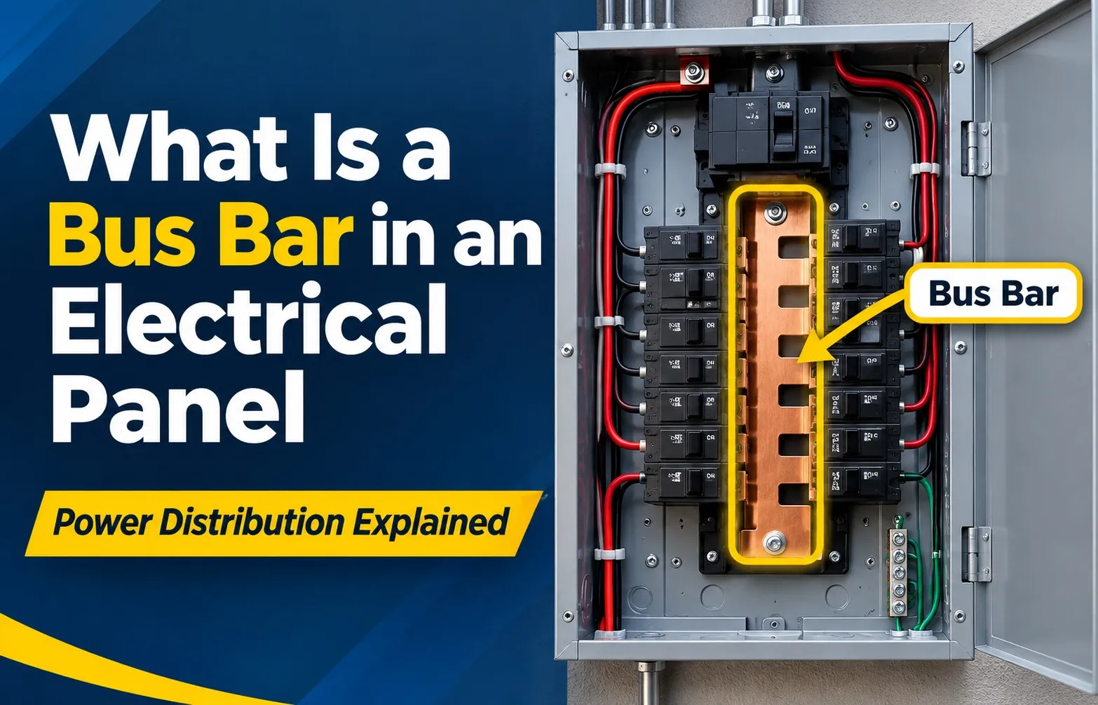 A bus bar (also spelled busbar) in an electrical panel is a thick, rigid metallic conductor—typically made of high-grade copper or aluminum—that distributes high-amperage electrical current from the main power feed to individual circuit breakers. It serves as the primary power distribution backbone within residential, commercial, and industrial breaker boxes.
The Electrical Distribution Backbone
The primary job of a bus bar is to streamline electrical distribution within your breaker panel while maintaining high efficiency and safety. It acts as a heavy-duty highway for electrical current, eliminating voltage drop and preventing dangerous thermal buildup.
- Central Power Reception: Main service cables connect directly to the panel’s main lugs or main breaker, feeding high-voltage current directly into the central bus bars.
- Low-Resistance Conduction: Because bus bars feature a large cross-sectional area, they carry massive electrical loads with minimal electrical resistance.
- Safe Breaker Mounting: Integrated metal tabs (bus stabs) extend along the length of the bus bar, allowing branch circuit breakers to snap directly onto live power safely.
- Balanced Load Splitting: In a standard split-phase electrical panel, two parallel bus bars split 240V incoming power into alternating 120V breaker slots to balance household circuits.
Why Modern Panels Use Bus Bars Instead of Wire Harnesses
Modern electrical codes and manufacturing standards mandate rigid bus bars over legacy wire harness assemblies. Solid metallic bars provide structural integrity, superior thermal dissipation, and enhanced electrical safety that stranded cables cannot match.
- Elimination of Wire Clutter: Running individual high-gauge wires to dozens of branch breakers creates a dangerous web of conductor insulation susceptible to overheating and short circuits.
- Superior Thermal Management: Solid copper and aluminum bars dissipate heat naturally across their metallic surface area, minimizing thermal expansion risks during peak electricity demands.
- Reduced Voltage Drop: Solid metallic bars maintain consistent voltage levels across all breaker slots, protecting sensitive home electronics from power sags.
- Standardized Modular Upgrades: Bus bars allow homeowners and licensed electricians to install, replace, or upgrade circuit breakers in seconds without rewiring the entire distribution grid.
How Electrical Bus Bars Work Inside Your Service Panel
Electrical bus bars operate as heavy-duty metallic rails that receive power directly from utility service lines and route it seamlessly across individual breaker slots. By substituting complex wiring bundles with solid, high-conductivity metal, they ensure steady electricity flow and reliable mechanical connections throughout the distribution system.
The Anatomy of Bus Stabs: How Breakers Connect
Breakers do not connect to bus bars via loose terminal screws or flexible wires; instead, they lock directly onto specialized metal protrusions known as bus stabs.
- Direct Interlocking Fit: The back of a standard plug-in circuit breaker features a reinforced spring-clip jaw that tightly grips the rigid copper or aluminum bus stab.
- High Contact Pressure: Tight contact friction prevents micro-arcing and overheating by maintaining maximum surface contact area between the breaker and the live rail.
- Secure Mechanical Anchoring: The bus stab not only supplies electrical power but also anchors the circuit breaker firmly to the panel backplate alongside mounting rails.
Amperage Load Distribution & Low Thermal Expansion
Bus bars are engineered with a specific cross-sectional area tailored to handle massive electrical currents—ranging from 100 amps to over 400 amps in residential and commercial service panels.
- Minimizing Voltage Drop: Solid metallic bars offer extremely low electrical resistance, preventing energy loss as power travels from the main breaker to branch circuits.
- Thermal Dissipation Properties: High-grade metals distribute thermal energy evenly across the bar structure, preventing localized hot spots under heavy household loads.
- Managing Ampacity Ratings: Each bus bar is rated to safely carry a maximum continuous ampacity limit determined by its thickness, width, and alloy composition.
120V vs. 240V Circuit Delivery in a Split-Phase Panel
In standard North American residential electrical panels, the bus bar architecture is structured around a 120V/240V split-phase utility configuration.
- Dual Phase Rails: Two parallel vertical hot bus bars (Hot Leg 1 and Hot Leg 2) run down the center or sides of the panel, each carrying 120 volts relative to the neutral line.
- Single-Pole Delivery (120V): Single-pole circuit breakers clip onto just one of the hot bus bars, powering standard lighting and general-purpose wall outlets.
- Double-Pole Delivery (240V): Double-pole circuit breakers bridge across both hot bus bars simultaneously, delivering 240 volts for heavy appliances like electric dryers, ranges, and central air conditioners.
The 3 Main Types of Bus Bars in a Panel & The Code Rules
An electrical panel is not powered by just a single metallic strip; it utilizes a coordinated system of specialized bars to distribute power, return current, and maintain safety grounding. Understanding these variations and National Electrical Code (Wikipedia’s overview of electrical busbars) requirements is vital for proper installation.
Hot (Phase) Bus Bars: Carrying Live Current
Hot bus bars are the primary energized conductors responsible for delivering high-voltage electricity directly into the branch circuit breakers.
- Live Power Delivery: Connected directly to the main breaker or utility service lines, carrying active voltage into the panel enclosure.
- Alternating Phase Arrangement: Designed in an alternating pattern so adjacent breaker slots hook onto opposite phases, allowing proper balancing of multi-wire and 240V circuits.
- Rigid Insulation Shielding: Heavily insulated or positioned behind safety barriers to prevent accidental contact by technicians or homeowners.
Neutral Bus Bar: Returning Current Safely
The neutral bus bar serves as the designated return path for electrical current flowing back from active 120V household loads.
- Completing the Circuit: Collects white neutral wires from individual branch circuits and channels the returning current back to the utility transformer.
- Current Carrying Duty: Unlike ground bars, neutral bars carry active, operational load current during normal electrical appliance usage.
- – **Terminal Screw Layout:** Features multiple individual screw terminals designed to accommodate stranded or solid copper and aluminum neutral conductors securely.
Ground Bus Bar: Fault Current Path to Earth
The grounding bus bar protects users and equipment by providing a safe, low-resistance pathway for stray electrical faults to travel harmlessly into the earth.
- Fault Diversion: Terminates bare copper or green insulated ground wires connected to appliance chassis, metal outlet boxes, and grounding electrodes.
- Non-Current Carrying: Remains completely inactive during normal operation, only carrying electricity when an internal insulation failure or short circuit occurs.
- System Earthing Connection: Anchored physically to the metal panel enclosure and wired directly to underground ground rods and metallic water pipes.
Main Service Panel vs. Sub-Panel: Bonding vs. Separation Rules
Adhering to strict National Electrical Code (NEC) guidelines regarding neutral and ground bus connection is legally and structurally mandatory for safety.
- Main Service Panel Bonding: In the primary utility service disconnect, the neutral bus bar and ground bus bar must be physically bonded together using a green bonding screw or jumper strap.
- Sub-Panel Isolation Mandate: In secondary sub-panels, neutral and ground bus bars must be strictly kept separate; neutral bars float on isolated plastic mounts while ground bars bolt directly to the metal enclosure.
- Preventing Parallel Paths: Separating neutrals and grounds in sub-panels prevents dangerous stray currents from traveling across equipment grounding conductors during normal operation.
Copper vs. Aluminum Bus Bars: Performance & Metallurgy
Choosing between copper and aluminum bus bars involves balancing electrical efficiency, thermal properties, physical weight, and long-term economic cost. Both metals dominate electrical panel manufacturing, but their distinct metallurgical profiles dictate how they perform under heavy industrial and residential loads.
Electrical Conductivity & Voltage Efficiency
Electrical conductivity is the primary metric governing how efficiently a bus bar transmits electrical current without losing energy as heat.
- Copper Superiority: Pure copper offers exceptionally high electrical conductivity, serving as the benchmark standard (100% IACS – International Annealed Copper Standard).
- Aluminum Requirements: Aluminum provides roughly 61% of the conductivity of copper, requiring a larger cross-sectional surface area to carry an equivalent ampacity load safely.
- Voltage Drop Mitigation: Because copper maintains superior atomic electron flow, it experiences less voltage drop across long transmission runs compared to aluminum alternatives.
Thermal Expansion, Anti-Oxidant Compounds, and Longevity
Metals expand and contract under fluctuating thermal loads, making mechanical stability and corrosion resistance critical factors in panel longevity.
- Thermal Expansion Coefficients: Aluminum expands more than copper when heated, which can loosen terminal connections over years of thermal cycling if not properly torqued.
- Galvanic Corrosion Risks: When dissimilar metals touch in the presence of moisture, galvanic corrosion can degrade the contact interface, increasing electrical resistance.
- Anti-Oxidant Joint Compounds (De-Ox): Aluminum bus bars require conductive oxide-inhibiting paste during installation to prevent non-conductive surface oxidation from forming at connection points.
Comparison Table: Copper vs. Aluminum Bus Bars
Troubleshooting: Signs of a Bad or Failing Bus Bar
Identifying a failing bus bar early prevents catastrophic electrical fires, unexpected power outages, and expensive panel replacements. Recognizing physical, audible, and olfactory symptoms allows homeowners and technicians to catch micro-arcing and overheating before structural failure occurs.
Visual Symptoms: Corrosion, Pitting, and Discoloration
Physical inspection of an electrical panel often reveals the earliest warning signs of bus bar degradation and terminal distress.
- Thermal Discoloration: Dark brown, black, or scorched metal patches on the copper or aluminum bus bar indicate chronic overheating and excessive resistance.
- Pitting Damage: Microscopic or visible surface pitting caused by electrical arcing slowly eats away at the conductive metal cross-section.
- Moisture Corrosion: White powdery oxidation on aluminum or green patina buildup on copper signals water ingress or high humidity inside the enclosure.
Operational Symptoms: Circuit Breakers Tripping or Loose Stabs
When bus stabs lose their structural spring tension or suffer physical damage, branch breakers begin to fail operationally.
- Loose Connections: Breakers that wobble or fail to lock firmly onto the bus stab create poor contact points, accelerating micro-arcing.
- Unexplained Tripping: Increased electrical resistance generates localized heat that triggers thermal-magnetic breaker trips even under normal loads.
- Burnt Breaker Casings: Removing a faulty breaker often exposes melted plastic around the rear clip jaw where it interfaces directly with the live bus bar.
Audible and Olfactory Clues: Humming, Buzzing, and Burning Plastic Odor
Your senses of hearing and smell provide immediate indicators of dangerous electrical faults happening inside a closed panel.
- Electrical Humming or Buzzing: A loud buzzing or crackling sound inside the panel often points to loose connections or electrical arcing across a damaged bus stab.
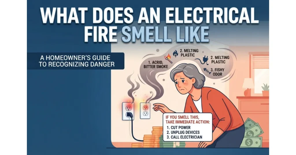
- Burning Plastic Odor: A sharp, acrid smell resembling melting wire insulation or hot bakelite is a critical emergency red flag requiring immediate power shutdown.
- Intermittent Power Flickering: Unstable contact on the bus bar causes voltage sags and flickering lights across multiple circuits simultaneously.
Critical Safety Warning: Working Near Live Bus Bars
Electrical service panels present extreme electrocution and arc flash hazards that demand absolute adherence to professional safety protocols.
- Main Breaker Limitations: Standard branch breakers only de-energize individual circuits; the main bus bars remain fully live with lethal voltage unless the main service disconnect is completely switched off.
- Professional Electrician Protocols: Never touch, probe, or clean internal bus bars without wearing certified arc-flash personal protective equipment (PPE) and utilizing insulated tools.
- Thermal Inspection Services: Hire a licensed electrician to perform non-contact infrared thermal imaging inspections to detect hidden bus bar resistance before visible failure occurs.
Frequently Asked Questions About Electrical Bus Bars
Common questions regarding electrical bus bars involve replacement feasibility, wiring regulations, ampacity limitations, and associated upgrade costs. Understanding these technical and safety guidelines helps homeowners and professionals maintain compliant electrical systems.
Can You Replace Just the Bus Bar in an Electrical Panel?
No, you typically cannot replace just a single bus bar inside a modern residential electrical panel. Panel manufacturers and safety testing standards certify the complete assembly as a single integrated unit, meaning a damaged bus bar almost always requires a complete panel upgrade.
- UL Listing and Certification: Electrical panels are tested and listed by Underwriters Laboratories (UL) as a single, factory-sealed system; modifying internal components voids this certification.
- Structural Integration: Bus bars are riveted, bolted, or molded directly into the insulated backplate framework, making isolated component swaps structurally impossible in modern panels.
- Liability and Code Compliance: Electricians and local inspectors will not sign off on partial bus replacements due to severe arc-flash liability and building code violations.
How Much Does It Cost to Replace a Damaged Bus Bar System?
Replacing a damaged bus bar requires a total electrical panel replacement, which typically costs between $1,500 and $4,000 depending on your location, panel amperage rating, and local permit requirements. The labor-intensive nature of disconnecting and rewiring every individual branch circuit drives the overall expense.
- Labor and Rewiring Time: Electricians must label, disconnect, and re-terminate every single circuit wire into the new panel enclosure.
- Permits and Inspections: Utility company coordination, municipal electrical permits, and mandatory safety inspections add to the total project cost.
- Associated Upgrades: Upgrading a damaged panel often triggers mandatory modern code updates, such as adding whole-home surge protection or exterior emergency disconnects.
Can You Double Up Wires on a Bus Bar Terminal?
Doubling up wires (frequently referred to as double-tapping) on a single bus bar terminal is strictly prohibited unless the specific terminal is explicitly rated and manufactured to accept two conductors. Violating this rule creates loose connections, excessive resistance, and severe fire hazards.
- Manufacturer Ratings: Most standard neutral and ground bar terminal screws are engineered to clamp down securely on only one single solid or stranded conductor.
- Thermal Expansion Loosening: Placing two wires under one screw prevents proper torque distribution, allowing thermal expansion to loosen one wire over time.
- Compliant Solutions: If extra terminal space is needed, an electrician must install an approved auxiliary ground or neutral bar accessory kit inside the enclosure.
Can You Use High-Gauge Cable Instead of a Bus Bar?
While heavy-gauge cables transfer power across electrical systems, they cannot replace a rigid structural bus bar inside a breaker panel. Bus bars provide secure mechanical bus stabs for circuit breakers, rigid structural support, and uniform current distribution that flexible multi-strand cables cannot physically accommodate.
- Breaker Mounting Stability: Circuit breakers require the solid, unyielding metal platform of a bus stab to snap securely into place and maintain high contact pressure.
- Heat Dissipation Efficiency: Flat, rigid metallic bars offer a massive surface area that radiates thermal energy much more effectively than bundled round cables.
- Spatial Constraints: Using loose cables inside a compact breaker enclosure would create chaotic wiring congestion and drastically increase short-circuit risks.
How Many Amps Can a Standard Panel Bus Bar Handle?
Standard residential electrical panel bus bars are engineered to handle continuous ampacity ratings of 100 amps, 200 amps, or 400 amps depending on the service size of the home. Heavy-duty commercial and industrial bus bar systems can safely carry thousands of amps.
- Residential Ratings: Modern homes standardly utilize 200-amp main service panels, featuring bus bars sized to accommodate total simultaneous household power demands.
- Cross-Sectional Sizing: The physical thickness and width of the copper or aluminum bar dictate its maximum ampacity without exceeding safe temperature rises.
- Continuous Load Margins: Bus bars are designed with safety margins to handle continuous electrical loads (running for 3 hours or more) without overheating.

Oscar Vance | Master Plumber & Drainage Expert
Meet Oscar Vance, a licensed master plumber sharing practical solutions on residential repairs, preventive maintenance, and thoughtful home upkeep.